

Anyone extruding aluminium profiles for windows and doors knows the rhythm of the line: the bar comes off the press, passes through the cooling table and the stretcher, and reaches the cut-to-length station in a flow that has no time for interruptions. Within this flow the identification marking — alloy, batch, cast, order reference — must find its place without becoming the station that slows everything else down.
The problem is not marking aluminium: a fibre source has been doing that with contrast and permanence for years. The problem is marking it while it moves, on a product that is by nature continuous and that often cannot be stopped bar by bar. This is where on-the-fly marking comes in, that is, marking on the move, synchronised with the real advance of the line.
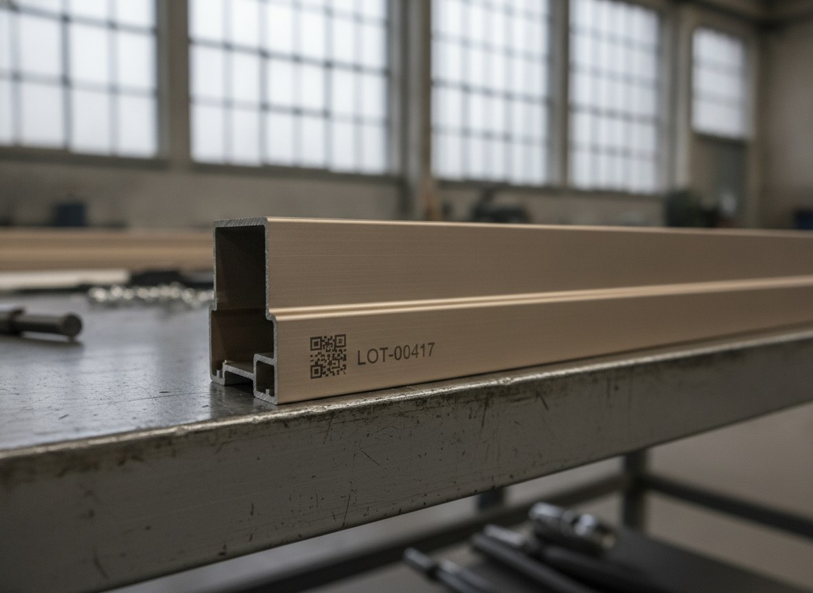
Marking on the move is not simply marking faster: it is a matter of synchronisation, of controlling graphic distortion and of integration with the stations upstream and downstream. Tackling it well means deciding where, how and at what speed the marking enters the extrusion process.
The continuous product that never stops
An extruded bar is not a discrete part that presents itself to the laser, stops, is marked and sets off again. It is a semi-finished product several metres long that runs along the roller conveyor at a speed set by the upstream stations. Stopping the advance to mark means introducing a build-up, a buffer or a dead time that propagates along the whole line. At low volumes this is acceptable; on continuous production it becomes the bottleneck.
It is the same logic that governs the marking of coil materials, where the strip does not stop: anyone familiar with continuous production on tape will recognise the same underlying constraint on the extruded profile. The difference is that here the substrate is solid, rigid metal, with a visible face that will end up under the eyes of the fabricator and the end customer.
Encoder synchronisation: what marking on the fly really means
On-the-fly marking relies on a simple and decisive component: an encoder mounted on the drive mechanism, which reports the linear displacement of the bar in real time. The marking controller reads this position moment by moment and shifts the deflection of the galvanometer head so that the beam follows the part as it draws each character. The text stays fixed relative to the metal even as the metal moves beneath the head.
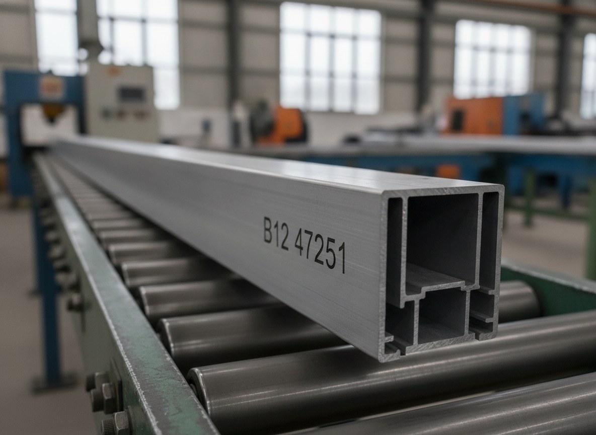
The critical point is that the speed must not be estimated, it must be measured: if the software works from a nominal speed while the line slows down or speeds up, the calculated position diverges from the real one and the marking shifts. The encoder closes this loop. The 1064 nm wavelength of the fibre laser and the galvanometer optics remain the same as in static marking: what changes is that the reference system is no longer the stationary part, but the dynamic coordinate supplied by the encoder.
Graphic distortion and the line’s speed limit
Without compensation, marking a moving part produces a typical artefact: the characters slant in the direction of travel, like an unwanted italic, and two-dimensional codes lose their orthogonality. On-the-fly compensation corrects this drift by reconstructing the geometry in dynamic coordinates, but the correction has a physical limit. Every marked element requires a minimum tracing time: the faster the line, the more the part advances during that time, and the harder the system has to chase it.
Beyond threshold: switch to stop&markThis gives rise to a threshold: up to a certain line speed the quality stays stable, beyond that threshold the usable window narrows and the result deteriorates, especially on dense content. A short alphanumeric string withstands higher speeds than a DataMatrix, which packs many cells into a few millimetres and demands more marking time to stay legible. Defining this threshold on the real content — not on a catalogue figure — is part of the commissioning work.
Anodised, painted or raw: how the marking changes
The window and door profile reaches the marking stage in three very different states, and each responds in its own way. On the as-extruded raw surface the fibre laser works through surface alteration and localised oxidation, producing a dark, permanent mark. On anodised profiles the beam acts on the oxide layer: on coloured anodised profiles selective colour removal leaves a clear contrast, while on natural anodised finishes it produces a lighter, matt mark. On the painted profile — typically a powder coating in a RAL colour — the laser removes the coating film, exposing the substrate.
These are well-established mechanisms on aluminium, and we covered them in detail in our in-depth piece on laser marking on aluminium. The practical consequence, on the line, is that the parameters are not the same for all three states: if the same line handles raw, anodised and painted profiles, the cycle must recall the correct parameter set according to the type of bar passing through.
Alloy, batch and choosing the non-visible face
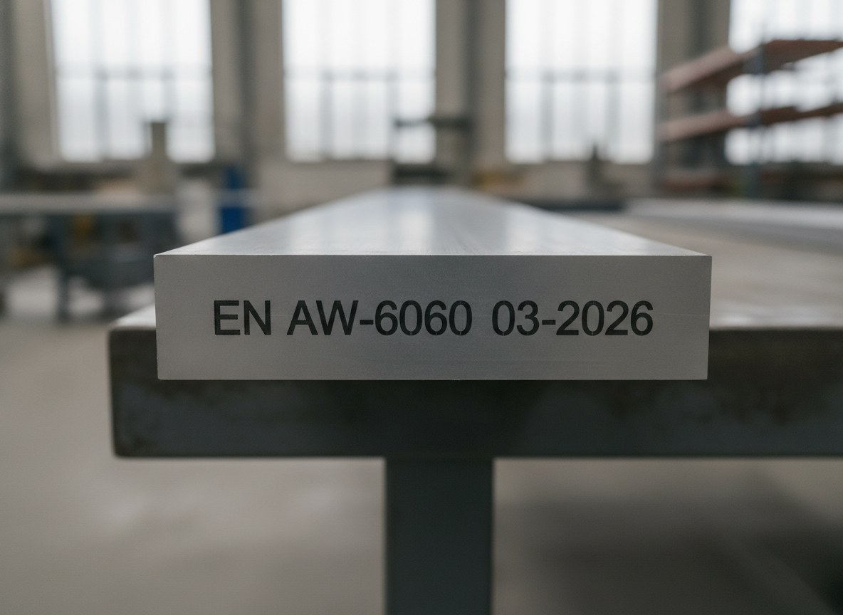
The content to be marked, in windows and doors, is almost always the same core of information: the alloy designation — on architectural profiles EN AW-6060 and EN AW-6063 predominate — cast number, batch and order reference. This data accompanies the profile towards cutting, assembly with thermal break and mechanical checks, and must stay associated with the right bar all along the chain.
Here comes a decision that is as much technical as it is aesthetic: where to mark. The profile has a visible face, meant to remain exposed once the window is fitted, and internal channels or grooves that disappear beneath gaskets, brush seals and joints. Placing the marking on a non-visible face preserves the appearance of the profile without giving up traceability: the code is there, legible during processing, but it does not compromise the visible finish of the completed window.
On legibility it is worth keeping a distinction clear: grading of the code is the quality check that can be applied in-line, whereas formal verification requires controlled laboratory conditions. In-line, grading is monitored to catch a degraded mark straight away; for the difference between the levels of checking we have devoted an article to the difference between reading, grading and verifying codes.
Integration with cut-to-length
On-the-fly marking makes full sense only if it talks to the neighbouring stations, and the most critical is cut-to-length. The continuous bar becomes lengths, and each length must carry its own identification: this requires coordinating the repetition of the marking with the cutting pitch, so that no cut piece is left without a code or carries one truncated halfway. On-the-fly marking makes it possible to write on the moving bar and to synchronise the information with the cutting logic, without dedicated stops.
It is the same principle by which marking, when well integrated, ceases to be an isolated station and becomes an intelligent node of the production line. On this kind of integration, where a laser to be inserted into the existing chain receives data and commands from the line controller, we have also described the case of a fibre laser integrated into a production line: the logic transfers from components to the continuous profile.
On-the-fly or stop&mark? Where the threshold lies (who it is meant for and who it isn’t)
The final question is an honest one: is marking on the fly really necessary? The answer depends on a comparison between two ways of working. In stop&mark the profile halts for the marking time and then sets off again: it is the simpler choice, it gives the highest quality because it marks on a stationary part, and it makes sense when the line can index, volumes are modest, format changes frequent or the content complex. In on-the-fly the bar never stops: it is the unavoidable choice when the extrusion is genuinely continuous and every stop propagates a build-up upstream.
The threshold, then, is not a universal figure but a crossing point of three factors: the throughput required, the real possibility of stopping the line and the density of the content to be marked. As long as the line tolerates micro-stops and volumes allow it, stop&mark remains the rational solution. When stopping costs more than the simplicity is worth, or when the flow admits no pauses, on-the-fly becomes the only viable route.
On-the-fly marking of aluminium profiles is designed for those who extrude continuously, mark alloy and batch on every bar and integrate a high-tempo cut-to-length downstream. It is not, however, the choice to chase for those working in short batches, with many profile changes and a line that stops anyway for other reasons: in that context a stop&mark station, simpler to manage, meets the need with less complexity. The right choice is decided on the process, not on the principle.

Business Development Director | LASIT
Business Development Director at LASIT, Giandomenico Ievoli is responsible for the commercial direction and strategic development of the company. He leads business development activities at national and international level, contributing to the growth and expansion of LASIT in global markets.


