

Anyone who manufactures wiring harnesses, sleeves, bushings and cable glands lives with a constraint that almost no other factory-marked part faces: the surface to be identified is also the wall that insulates. A serial number, a batch code, a circuit designation or a voltage rating must remain legible for the entire life of the component, yet the mark cannot remove material from a wall just fractions of a millimetre thick, whose job is to keep a conductor separated from everything around it.
Traditional methods sidestep the problem without solving it. Printed cable ties and adhesive labels add an element that can peel off, rotate along the cable or fade; pad printing and inks deposit a layer that abrasion, solvents and high temperatures wear away. The laser, by contrast, marks the polymer directly, with no consumables and no contact — but on plastic precisely, the margin between clean contrast and damage to the wall is narrower than on metal.
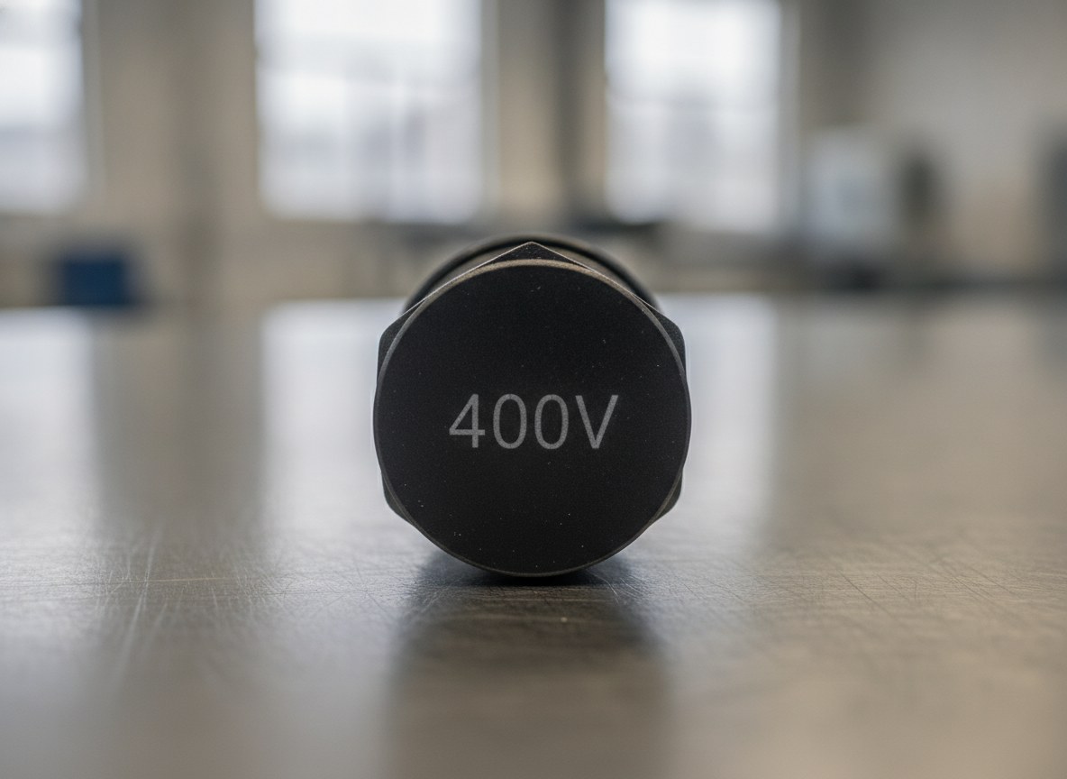
The key, on these materials, is to treat the marking as a controlled contrast: a targeted alteration of the very topmost layer of the polymer that generates legibility without impairing the insulating function. It is a question of material and parameters, even before it is a question of machine.
Why the insulating wall changes the rules
On a metal component the marking can afford to remove a few microns or to oxidise the surface: the part remains structurally the same. On a sleeve or a cable gland it cannot. The usable thickness is the one that guarantees the dielectric strength, and every groove that removes material locally reduces that reserve. The ideal mark, here, is not an engraving but a colour change of the outer layer, achieved with the minimum energy needed to make it visible.
This reverses the logic compared with marking on metal. The aim is not depth, but contrast at constant integrity: maximising the colour difference between mark and background while keeping the heat input and the material removal within a limit that does not touch the load-bearing wall. Every choice of source, wavelength and parameters starts from here.
How PVC, polyolefins, silicone and heat-shrink materials react to the beam
There is no such thing as “the plastic”: each polymer family responds to the laser in its own way, and the choice of source starts from this.
PVC absorbs the radiation well and reacts with contrast even at low energy; the critical point is not markability but its halogenated nature, which we discuss further on. Polyolefins — polyethylene and polypropylene, the most widespread bases for sleeves and corrugated conduit — are largely transparent to the wavelength of the fibre laser (1064 nm): without absorbing additives they tend to melt or foam rather than mark cleanly, and this is the case in which the UV (355 nm) wavelength, which acts on the polymer bonds rather than through heat, gives the best contrast. Silicone is thermally stable but soft and elastic: it responds well to a marking by surface lightening, provided the energy stays low so as not to score the elastomer. Heat-shrink materials add a unique constraint: they are designed to shrink with heat, so an excessive heat input during marking can pre-activate the shrinking right in the area of the code, distorting it — which is why on these materials short pulses and moderate power densities are preferred.
| Polymer | Laser response | Main consideration |
|---|---|---|
| PVC | Good contrast even at low energy | Halogenated fumes: dedicated extraction |
| Polyolefins (PE, PP) | Poor absorption at 1064 nm: UV or additives preferable | Tendency to melt or foam |
| Silicone | Contrast by surface lightening | Low energy to avoid scoring the elastomer |
| Heat-shrink materials | Contrast with short pulses | Heat can pre-activate the shrinking |
The practical consequence is that a single set of parameters does not cover the entire bill of materials of a wiring harness. Sleeves, bushings, cable glands and heat-shrink tubing may call for different recipes, which is why defining the cycle almost always goes through trials on real samples of the material actually in production, not on generic test pieces — the same care required by the marking of plastics in the electronics sector.
Contrast on black: additives, pigments and the role of UV
Most sleeves and cable glands are black, mass-coloured with carbon black. On a background this dark, contrast is not obtained by darkening — it is obtained by lightening: the beam locally alters the pigment and the polymer matrix, producing a light, grey or whitish mark, through foaming or bleaching of the pigment. It is a surface mechanism, living in the first few layers and with no need to dig.
Here the role of additives and wavelength is decisive. Some compounds already contain additives that promote the marking reaction; on poorly absorbing materials the UV source for marking plastics works photochemically and achieves sharp contrast with a reduced thermal load, an advantage when the wall is thin and the risk of distortion is high. On more absorbing polymers the fibre laser remains effective and productive. The logic is always the same: to choose the combination that gives maximum contrast with minimum physical alteration.
The risk of excessive removal and the thickness that can be taken away
The danger, on these components, is pushing the energy beyond the contrast threshold and entering the ablation regime: at that point the beam no longer colours, it digs. On an insulating wall this means eroding the thickness that guarantees the dielectric seal, with damage that is often not visible to the naked eye yet compromises the function. There is a threshold below which the laser only transforms the colour and above which it begins to remove material: all the setup work lives in staying below that threshold with a good margin.
The safety criterion is to define, during trials, the maximum energy — and therefore the maximum depth of alteration — compatible with the thinnest wall present on the part, and to work steadily below it. The check is not done by eye: the marked sample is cut and the cross-section is examined under the microscope to measure how deep the alteration has reached relative to the remaining thickness, backing up the measurement with a dielectric-strength check on the samples. It is a laboratory step, to be carried out once when validating the cycle, not part by part.
Continuous marking on the coil, an alternative to printed cable ties
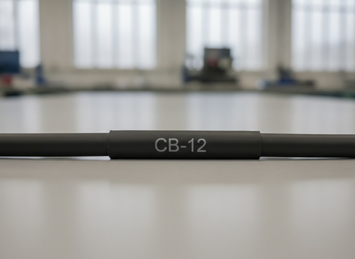
On cables and sleeves managed by the metre, traditional identification goes through printed cable ties and tags applied downstream. These are added elements that have to be managed in the warehouse, applied by hand, and that can peel off or rotate. Continuous laser marking reverses the approach: the code — sequential serial number, designation, batch reference — is marked as a contrast directly onto the sleeve while the cable runs, at regular intervals along the whole coil.
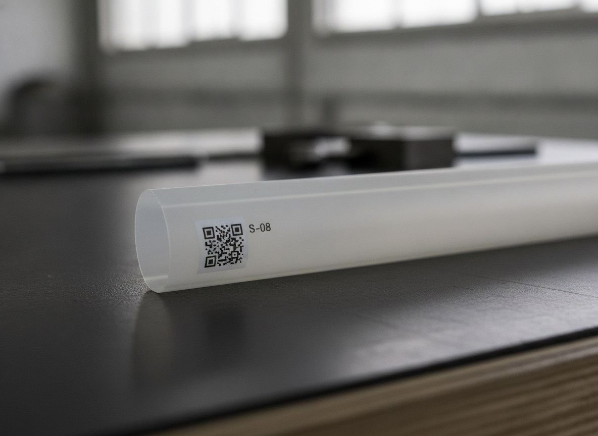
The mark is part of the cable, not an accessory: it does not peel off, does not shift and stays consistent along the entire length. It is the same need for traceability that is driving electrical components away from pad printing towards direct, stable marking. Where a richer piece of data is needed — a DataMatrix pointing to a batch or a bill of materials — the code can be marked on a plate fixed to the connector or the harness, keeping the same logic of permanent legibility.
PVC and halogenated polymers: the question of fumes
There is one aspect that cannot be ignored on wiring: many insulators, starting with PVC, are halogenated polymers. When the laser processes them, the gaseous by-products contain chlorine compounds that are corrosive to the machine’s optics and irritating to those working on them. This is not a marginal detail: it is a process condition that must be managed at source.
The answer is an extraction and filtration system sized for the material, with filters suited to capturing the particulate and neutralising the acidic compounds. This is why, when marking PVC and similar materials, fume extraction is not an accessory but an integral part of the system: it protects the operator, keeps lenses and optical surfaces clean and stabilises marking quality over time.
Who it is designed for (and who it is not)
Laser marking as controlled contrast is the natural choice for those who produce sleeves, bushings, cable glands and wiring and need permanent identification that adds no elements and does not touch the insulating function: serial numbers, circuit designations, batch references and voltage ratings that must survive handling, heat, oils and solvents for the entire life of the installation. On black components, on poorly absorbing materials and on heat-shrink tubing, the right combination of source and parameters delivers legibility without removal.
It is not, however, the simplest route when the wall is too thin, so that even a surface alteration erodes an already scarce dielectric margin, or when the material is a compound not designed for marking and the contrast turns out weak: in these cases you act first on the material — choice of polymer or of markable additives — and only afterwards on the laser. And it remains a method that must be validated: without trials on real samples and without cross-sectional verification of the altered thickness, no parameter should be taken for granted.
In short: if identification must be permanent, integrated into the part and respectful of the insulating wall, laser marking treated as controlled contrast answers exactly this problem — provided you choose source, parameters and extraction to suit the polymer, and verify its effect where it counts, namely in the thickness.

Applications Manager | LASIT
Applications Manager at LASIT for over 20 years, Mario Palmieri oversees the management and development of the company’s laser laboratory. He is responsible for conducting sample tests for customers, supporting the automotive, medical, aerospace and electronics sectors in identifying the most suitable laser marking solution for their needs.


