

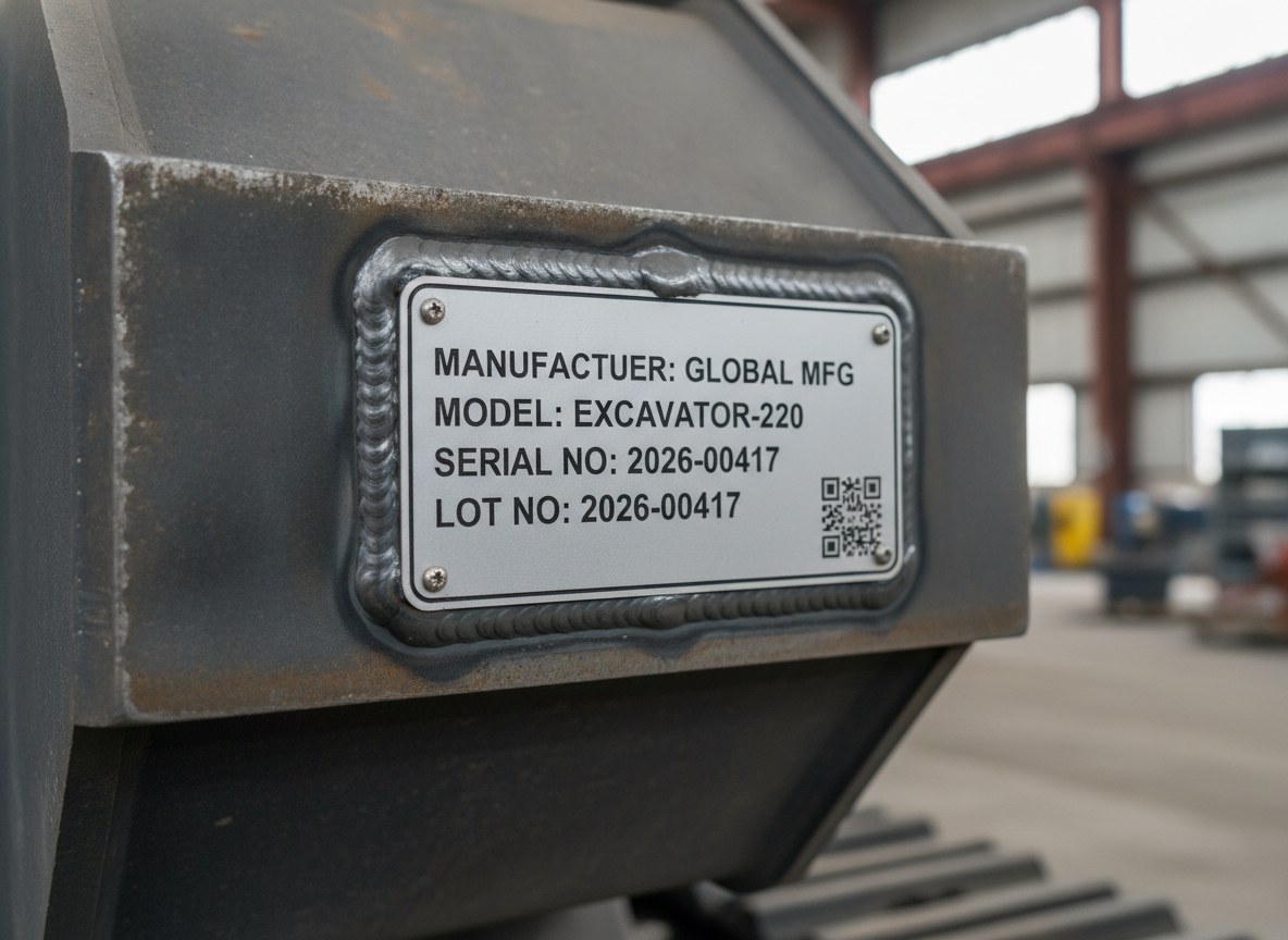
Those who design and build frames, arms, side members, buckets and chassis for earth-moving and agricultural machinery work every day with welded structures that weigh hundreds of kilograms and easily exceed a metre and a half in size. Marking is the last operation in the cycle, but it is the one that imprints on the component the data destined to last for its entire life: manufacturer identifier, serial number, batch references and the nameplate data required for compliance. On these parts, marking steel is not the problem — a 1064 nm fibre laser has been engraving raw carbon steel without difficulty for decades.
The problem is reaching it. An excavator arm or a tractor side member will not fit into a standard marking enclosure, and handling it means an overhead crane, slings and downtime that fragments the cycle. On a large part, the constraint is not the physics of marking but the access geometry: where the point to be marked is located, how the beam reaches it and how the code is read once the metal is welded, oxidised and covered in mill scale.
The logic is reversed: when the part cannot go to the laser, it is the laser that must go to the part. It is around this choice that the right system is built.
The constraint is not the metal, it is the accessibility of the marking point
On a bench component the marking point is always in focus, beneath the head, perpendicular to the beam. On a welded structure weighing several hundred kilograms this condition has to be created: the point to be marked may be on a plate recessed between two cross members, on the back of an inclined arm or on a downward-facing flange. The operator cannot rotate the part as they would with small components, and every repositioning with the overhead crane introduces play and downtime.
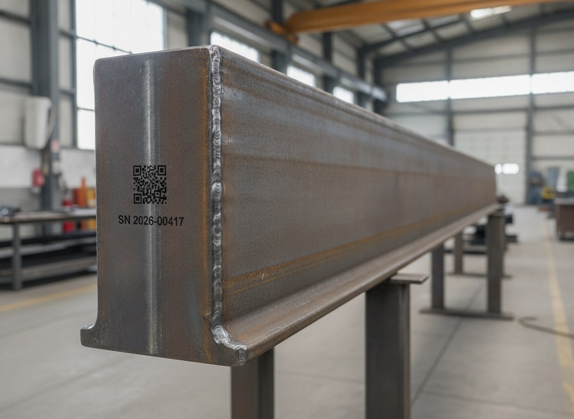
This is why the assessment starts from the physical map of the part: overall dimensions, weight, centre of gravity, and above all the position and orientation of the marking area relative to how the component arrives at the workstation. Two frames with the same nameplate data, but with the identification plate positioned differently, require different access solutions. This is a manufacturing consideration, not a laboratory one.
Bringing the beam to the part: gantry, robot and large-volume enclosures
When the component is too large or too heavy to be handled, the system takes on the movement. There are three routes and they are often combined. The first is the gantry structure: the marking head moves on motorised axes above a wide working plane, reaching distant areas without touching the part, which stays where the overhead crane deposited it. This is the approach of large-format machines such as Fly Gantry MAG, designed precisely to work on oversized dimensions.
The second is robotic integration: an articulated arm brings the scanning head to the point to be marked, following paths that navigate around complex geometries — useful when the marking area faces awkward directions. The third is the large-volume enclosure with assisted loading: systems such as TowerSwipe, with side loading, are designed to allow heavy and bulky components in and out without lifting them over a threshold. In every case, marking can be managed as a stand-alone station or integrated in line, downstream of welding or surface treatment.
On extended marking fields, where a deep part presents different focal heights from point to point, hybrid configurations combining XY axes with pre-scan are adopted: the motorised axes cover the travel, while the head manages dynamic focusing along the surface. This is the correct way to keep the beam perpendicular and in focus without sacrificing the working area.
Nameplate data and compliance: what must remain legible
On an agricultural or earth-moving machine, marking the structural components serves a documentary function. The manufacturer’s company name, serial number, model references and the nameplate data required by the machine’s compliance appear on the frame or identification plate. This information accompanies the component throughout the entire supply chain and must remain legible after painting, exposure to the elements, mud, impacts and high-pressure washing.
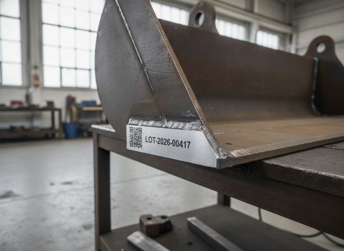
Here, direct laser marking has a structural advantage over labels and stamping: it is part of the metal, not a layer applied on top. A DataMatrix code engraved to sufficient depth survives cycles that a label cannot withstand, and remains uniquely associated with that single part. The question of code quality verification — the distinction between simple reading, in-line grading and laboratory verification — is decisive when the data must be guaranteed along the supply chain, as we explored when discussing the difference between reading, grading and verifying codes.
Reading on welded and oxidised surfaces
The surface of a welded structure is anything but regular. Weld beads, mill scale, oxide, oxy-cutting traces and uneven roughness create a background on which the contrast of the marking is not a given. A code engraved on a freshly welded edge may sit next to a heat-affected zone with completely different reflectivity, and this tests both the marking and the subsequent optical reading.
The answer lies in the process, not in brute force. The fibre laser generates contrast through localised removal and alteration of the material, and the choice of parameters — spacing, fill, number of passes — must be calibrated on the actual background, not on an ideal sample. Where needed, the marking area is prepared with a laser cleaning pass that removes oxide and mill scale before engraving the code, restoring a uniform surface that raw metal does not offer. The result is a DataMatrix with crisp modules, readable by an industrial scanner even after years and exposure to the weather.
Curved or inclined geometries add a further layer: marking over a wide field with variable angles of incidence degrades the code quality. The techniques for maintaining focus and perpendicularity on non-flat surfaces are the same that govern marking on curved and irregular surfaces, and on a welded structure they become an integral part of the marking design.
| Aspect | Direct marking on the part | Applied metal nameplate |
|---|---|---|
| Accessibility of the point | Requires a gantry, robot or large-volume enclosure | Marked separately, under controlled conditions |
| Surface quality | Welded and oxidised background, may require preparation | Perfect plane, uniform contrast |
| Reading and grading of the code | To be validated on the actual background | Simpler and more repeatable |
| Traceability | Code part of the metal, no applied element | One extra link: fixing and risk of detachment |
Direct marking or an applied nameplate
Direct marking on the part is not always the best route. When the point to be marked is entirely inaccessible, when the surface is too irregular to guarantee reliable grading, or when the manufacturer wants a standardised data plate uniform across the whole range, the metal nameplate marked separately and then fixed to the component remains a technically valid solution.
The nameplate is marked under controlled conditions, on a perfect plane and at constant focus, which greatly simplifies the reading and grading of the code. The downside is that it introduces an applied element — with its fixing, the risk of detachment and one extra link in the traceability chain. The choice between direct marking and a nameplate is not ideological: it depends on the accessibility of the point, the surface quality and the documentary requirements. Often the most robust solution combines the two, with nameplate marking handled by the same system that marks the part.
How the accessibility of the marking point is assessed, right from the quotation
The typical mistake, when starting a marking project on large structures, is to reason first about the source and then about the access. This is the reverse of the correct order. The question to ask at the quotation stage is: where is the point to be marked, how does the part arrive at the workstation and with what movement — of the part or of the beam — is it reached in focus and perpendicular.
This is why a serious assessment starts from the component drawings and from real samples: the marking area is mapped, the dimensions are checked, the choice is made between gantry, robot or large-volume enclosure, it is established whether the surface requires preparation and the reading of the code is tested on the actual background, welded and oxidised. Defining these points before supply avoids discovering in production that the robot arm cannot reach, or that the DataMatrix cannot be read on the weld bead. The accessibility of the marking point is a design requirement, exactly like the serial number to be engraved.
Who it is designed for (and who it is not)
This approach is the natural choice for those who produce heavy and bulky welded structures — frames, arms, buckets, chassis, side members for earth-moving and agriculture — and need permanent nameplate data and traceable codes on raw, welded and oxidised steel. It is designed for those who currently move enormous parts to a marking station and pay for that transfer in time and complexity.
It is not, however, the right answer for those who mark small, easily handled parts, where a bench or rotary-table machine remains faster and more efficient in cycle terms, nor for those with volumes high enough to warrant a cell dedicated to a single repetitive component. In short: if your part does not fit into an enclosure and the point to be marked is hard to reach, the real issue is not which laser to choose, but how to bring the beam to the part and how to read the code where the metal is least cooperative. That is where the success of the project is decided.

Business Development Director | LASIT
Business Development Director at LASIT, Giandomenico Ievoli is responsible for the commercial direction and strategic development of the company. He leads business development activities at national and international level, contributing to the growth and expansion of LASIT in global markets.


