

Anyone who produces die-cast components in zamak or aluminium alloy will recognise a recurring scene at the end of the line: the very same marking recipe that left a crisp DataMatrix and a satisfied scanner on the part just marked returns, on the next part, a washed-out, patchy code, with entire areas that disappear against the background. No one has touched the parameters, yet the contrast has changed.
The instinctive reaction — turn up the power, slow the scan down, dwell on the same spot — almost never solves it, and often makes things worse. The reason is that the variability does not originate in the machine: it originates in the part. The surface of a raw casting is not as uniform as that of a rolled or turned part, and the laser marks exactly what it finds beneath the beam, defects included.
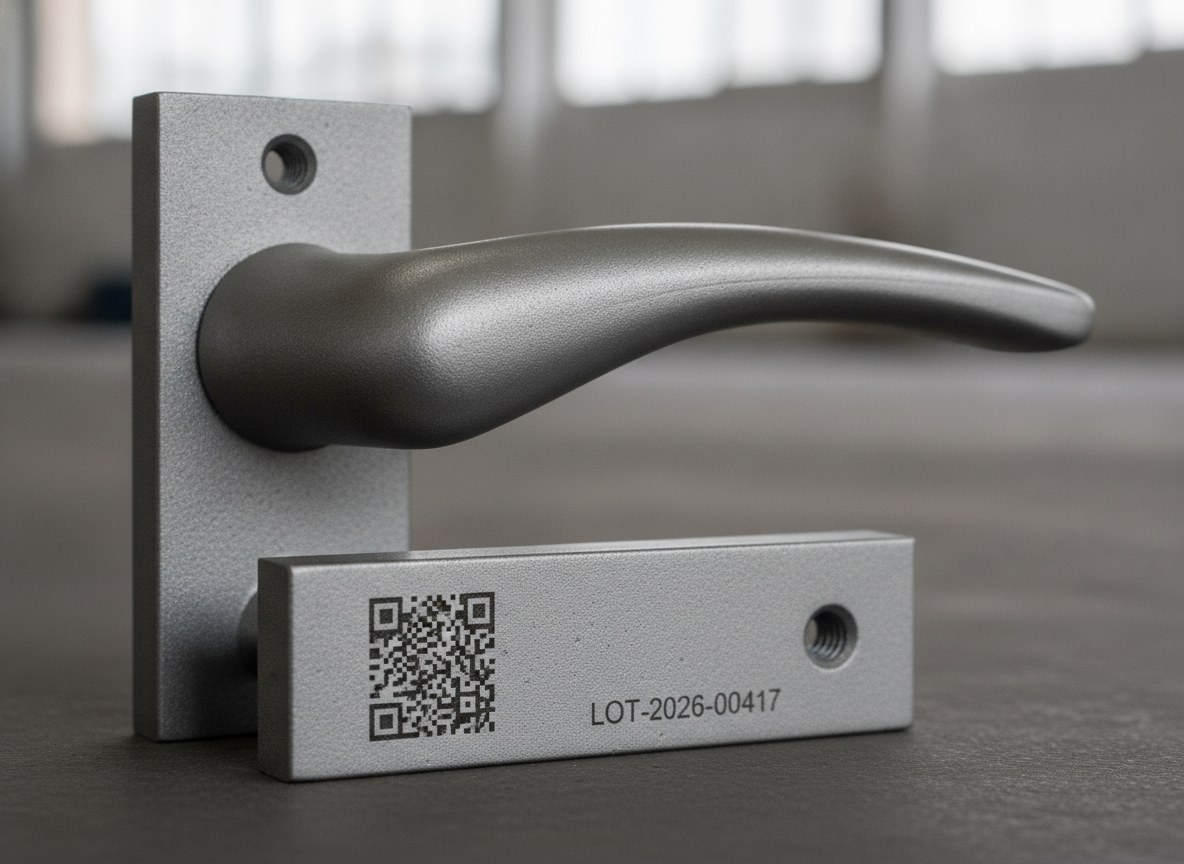
Insufficient and uneven contrast on die-cast parts is, first and foremost, a metallurgical and surface defect, not a calibration error. Tackling it means changing the marking strategy and, when necessary, moving the point at which you mark — not chasing a perfect parameter that, on that raw casting, does not exist.
The skin effect: why a raw casting is not a homogeneous surface
Every part that comes out of the mould carries a casting skin with it: a thin surface layer, but a decisive one for marking, formed during solidification in contact with the wall of the die or mould. This layer is chemically different from the core of the part — richer in oxides, release-agent residues and trapped microporosity — and its thickness and compactness vary from area to area and from cast to cast.
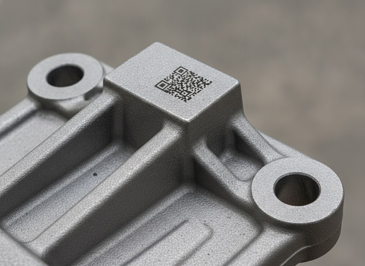
The laser interacts with the first few microns of the material. When marking takes place by oxidation or annealing, the contrast is the result of a controlled reaction on that outer layer: if the layer changes — because there is sub-surface porosity beneath the beam, a lifting of the skin, an alloy segregation — the colour that comes out changes too. It is the same principle by which an impeccable mark on a polished sample behaves unpredictably on a raw casting fresh from the die.
It is therefore not a problem of machine repeatability, which on any single point remains constant, but of the repeatability of the surface. It is a distinction that completely changes the approach: you do not chase the calibration, you design the marking taking into account how the part is made. The same reasoning that guides laser engraving in the foundry industry applies, with different constraints, to contrast as well.
Why increasing the power does not solve it (and often makes it worse)
The most common temptation is to turn up the power to “force” the contrast on difficult parts. On a raw casting this produces the opposite effect. Beyond a certain threshold the beam does not blacken more: it punches through the casting skin, opens up the porosity below the surface, and generates craters, burrs and specular reflections that disturb the very optical reading you were trying to improve.
Laser power Mark contrast beyond the skin porosity opensThe contrast between mark and background depends on the quality of the surface reaction, not on the depth of the removal. A deeper groove on a porous alloy creates shadows and jagged edges that a scanner interprets as noise, not as data. Adding energy means adding heat, and on zamak and die-cast aluminium more heat means more local melting, more halos and more visual variability — the exact opposite of the uniformity that is needed. The right lever is not depth: it is how the energy is distributed across the surface.
Increase the area, not the depth: fills and hatch
The strategy that gives the most stable results on the raw casting goes in the opposite direction to deep engraving: widen the footprint and work at low energy over a larger area. Marks with a dense hatch, fills made of several light passes and a slightly widened focus average out the local irregularities: where one point falls on a pore, the next one falls on sound material, and to the eye as to the scanner the code module still comes out full and uniform.
It is a contrast obtained by extent and averaging, not by cutting. The characters and modules of the DataMatrix should be sized generously enough to absorb the granularity of the raw casting, avoiding thin strokes that a single pore can interrupt. The same logic of controlling the energy input that applies to laser marking on aluminium becomes the guiding criterion here, because the die-cast alloy is less predictable than its wrought version.
In this scenario the source matters. A MOPA source, being able to vary the pulse duration, allows you to calibrate the surface reaction to obtain controlled greys and blacks without bringing the area into melting — a valuable adjustment margin on surfaces that change from one part to the next. On why the adjustable pulse makes the difference, I refer you to the comparison between MOPA laser and fibre laser.
Marking on an already machined area: the most reliable strategy
When readability is a requirement and not a nice-to-have — a traceability DataMatrix that must be graded on the line — the most robust solution is not to optimise the marking on the raw casting, but to take the raw casting out of the equation. Providing, at the mould design stage, a small faced or milled pad at the marking point removes the casting skin and exposes homogeneous material: the surface becomes repeatable, and with it the contrast.
Design for reliable markingCastingMachined padLaser markingIn-line gradingIt is a principle of design for marking: markability is decided upstream, when the cavity is designed, not downstream when the part is already cast. A pad of a few square centimetres, already provided for in the drawing, costs far less in terms of scrap and rework than a mark that passes grading one batch and fails the next. Where the cycle already involves a machining operation, marking on a machined face is almost always the right choice.
Zamak and die-cast aluminium: two behaviours to be treated separately
Treating “die-cast parts” as a single category is a mistake. Zamak, a low-melting-point zinc alloy, tends to reflow and form halos easily: it calls for narrow, well-controlled energy windows, because the margin between a clean mark and a molten surface is small. Die-cast aluminium, with its silicon content and the gas porosity typical of the process, presents a surface that is instead more heterogeneous point by point, where the risk is local unevenness rather than widespread melting.
It follows that the recipe must be built per alloy and, ideally, validated on the real parts of that specific production — not transferred from one material to another. The temperature of the part also has an impact: marking components while they are still hot introduces a further variable on contrast, an aspect we addressed when discussing marking on hot foundry parts.
Cast-batch traceability: what really needs to be read
On die-cast parts the marking almost always serves to carry the identity of the cast downstream: batch number, mould, cavity, date. These are the data that make it possible, when faced with a defect, to quickly isolate the production involved instead of halting everything. For this to work, the code must not only be marked: it must pass an objective check.
This is where grading comes in, the assessment of code quality according to recognised standards (ISO/IEC 15415 and AIM DPM for direct marking), applicable on the line to set a repeatable acceptance threshold. It is worth remembering that in-line grading and laboratory verification are two distinct things: verification requires controlled conditions and dedicated instrumentation, whereas grading is the standard you take into production. We have devoted an in-depth piece to this difference, on the difference between reading, grading and verifying codes. On a variable raw casting, in-line grading is what turns “it looks readable” into a measurable criterion.
When the raw casting cannot be marked reliably (and it pays to move the point)
There is an honest limit to acknowledge: some raw castings cannot be marked reliably, full stop. If the casting skin is too irregular, the surface porosity pronounced and no machined area is planned, no parameter will guarantee a repeatable contrast at grading. In these cases the right technical choice is not to persist, but to move the moment of marking.
It is often better to mark downstream of an operation that returns a stable surface: after shot peening or sand blasting, after machining, or else after painting or coating, where a contrast obtained by selective removal of the film becomes markedly more predictable. Alternatively, when not even this is feasible, traceability is assigned to a dedicated nameplate. This is not giving up: it is placing the marking where the process makes it repeatable.
In short, on the contrast of die-cast parts the right question is not “how much power is needed”, but “which surface am I marking on and can I make it more uniform”. Recognising that the origin of the problem is metallurgical — and acting accordingly on the marking area, the area to be struck and the point in the cycle — is what takes you from a code that sometimes reads to a code that always reads.

Applications Manager | LASIT
Applications Manager at LASIT for over 20 years, Mario Palmieri oversees the management and development of the company’s laser laboratory. He is responsible for conducting sample tests for customers, supporting the automotive, medical, aerospace and electronics sectors in identifying the most suitable laser marking solution for their needs.


