
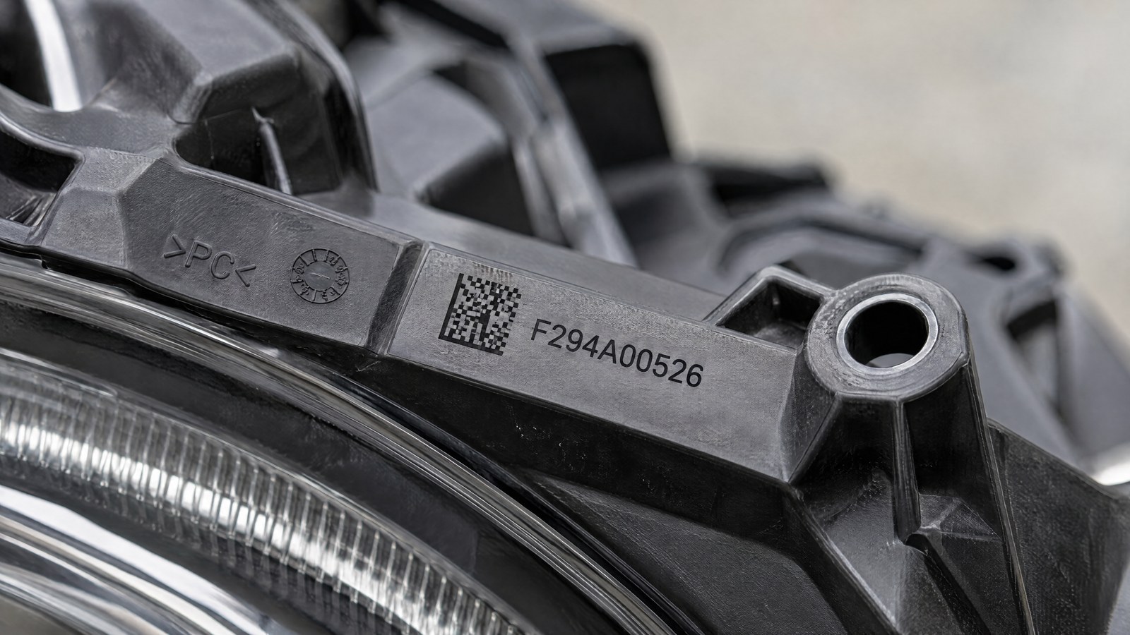
Anyone assembling headlamps and optical assemblies for the automotive sector knows the constraint: every headlamp body and every lens must carry a traceability code — DataMatrix, part number, batch — that follows the component along the supply chain and holds up to a possible recall. But an optical assembly is, first and foremost, a system that has to transmit and distribute light in a controlled way. A mark in the wrong place deflects a beam, creates a shadow or a reflection, and compromises both the function and the appearance of a component that the end customer sees every time the headlamps are switched on.
The question is not whether to mark, but where and how: the code must be permanent and readable by an in-line scanner without touching the optical area or altering light transmission. On transparent polymers such as PC and PMMA, moreover, achieving contrast without weakening the part is anything but straightforward. Laser marking meets these requirements together, provided three things are decided: the area of the part, the source according to the polymer, and a readability check that keeps pace with the line.
Where the code goes: everything outside the optical area
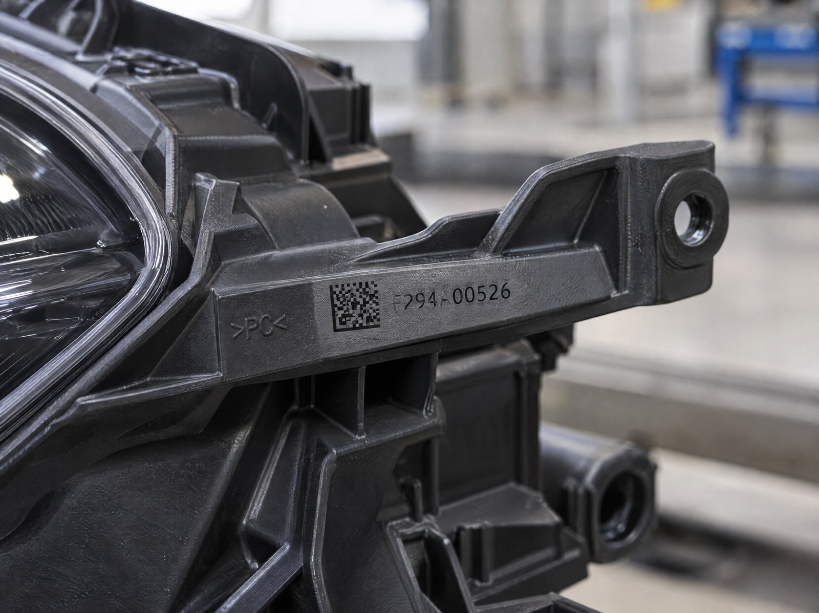
The layout rule comes before the technology. On an optical assembly the surfaces fall into two families: those that work the light — the optical face of the lens, the paraboloid or the facets of the reflector, the metallised zones — and everything else: fixing flanges, stiffening ribs, perimeter edges, screw bosses, mounting tabs. The code goes exclusively on these latter ones, on a flat, non-illuminated area, ideally one already hidden from view in the assembled vehicle.
Marking on the optical face is ruled out: even a small DataMatrix becomes a defect that deflects or scatters the light. On transparent lenses the code is placed on the perimeter edge or on a tab outside the illuminated field; on dark plastic bodies, on a rib or a flat edge, alongside the mould markings already present. The DataMatrix remains the standard because it concentrates part number and batch into a few square millimetres — a now well-established choice for traceability with 2D codes — leaving the usable surface free.
The source changes with the polymer
This is where the physics of the material comes in. Headlamp bodies often use polycarbonate or glass-fibre-filled engineering plastics such as PA and PBT; lenses are made of PMMA or optically transparent PC. Each family reacts differently to laser light, and the source must be chosen accordingly.
On transparent polymers the reference is the UV laser at 355 nm. The short wavelength works mainly by a photochemical route: it breaks the molecular bonds at the surface with a limited thermal input and produces a micro-foam mark or a sharp, well-defined colour change, without burning or deforming the optically critical material. This is the same principle that makes UV the most robust route for UV marking of PMMA in automotive lighting.
| Polymer of the optical assembly | Behaviour under marking | Recommended source |
|---|---|---|
| Transparent polycarbonate (PC) | Colour change and surface micro-foam | UV |
| PMMA (lenses) | Light micro-foam, low thermal input | UV |
| Filled plastics (glass-fibre-filled PA/PBT) | Light foaming contrasting against the dark background | Fibre / MOPA |
On filled plastics and dark engineering polymers, instead, a fibre source at 1064 nm, or in the MOPA version with adjustable pulse duration, produces light foaming that stands out in contrast against the dark background. Parameter setting is decisive: additives, mineral fillers and pigments change the response from batch to batch, and the same polymer from two different suppliers may require a distinct set of parameters.
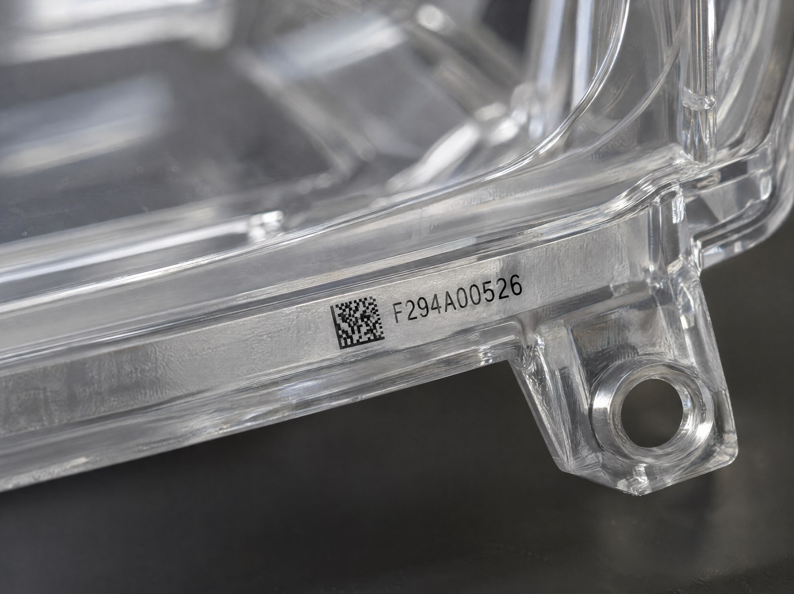
Contrast without pigments: the mark is born within the material
On a transparent part, contrast is the real problem: there is no coloured background to print on. The mark has to be born inside the material, as micro-foam or local alteration, deep enough to be read by a scanner but shallow enough not to trigger micro-cracks that propagate over time.
A deep engraving on PMMA or PC is counterproductive: it weakens the part and can become a fracture initiation point under thermal stress. The aim is the minimum mark that guarantees reliable reading, not the most pronounced mark possible. On these materials the quality of the marking is decided by fine control of the energy, not by depth.
In-line readability: grading is not laboratory verification
A code that the operator sees clearly is not necessarily a code that the scanner always reads. That is why readability is measured, and it is measured in line. In-line grading assigns a quality class to the DataMatrix immediately after marking, using the same camera as the system, and rejects the part before it moves on to assembly.
This is different from laboratory verification, which requires controlled lighting and instrumentation conditions and serves to validate the process, not to check every part: it is precisely the difference between reading, grading and verification of codes. In production both are needed, with distinct roles: verification qualifies the cycle, grading keeps it under control part by part.
Line-cycle code controlMarkingReadingIn-line gradingMarking before assembly, at the right point in the cycle
The right moment to mark is before body and lens become a closed assembly. Marking housing and lens separately, at a dedicated station, makes it possible to reach the flat area with the beam perpendicular and to read the code without the optical interference of the already-assembled part.
On automotive lighting lines, marking often coexists with other laser operations on the same component, such as the selective ablation of metallised zones: integrating them into a single flow reduces the steps and the risk of data misalignment between stations.
Who it is designed for (and who it is not)
This approach is designed for those who produce or assemble optical assemblies in volume and must guarantee traceability on optically critical components: headlamp bodies in engineering plastic, lenses and light guides in PC or PMMA, where the code must exist but must not be noticed by the light. On transparent materials UV remains the safest route for contrast and integrity; on filled plastics, fibre or MOPA.
It is not, however, the right answer when traceability can live on a label applied downstream, outside the optical assembly, or when the component has no available non-optical surface: cases in which it is worth rethinking the layout of the part before marking. And if the requirement is a visible decorative mark on the visible side of the lens, the subject is no longer traceability but decorative finish, with different constraints and process choices.
In short: if the optical assembly must be traced permanently and read in line without the code ever touching the light, the problem is solved by choosing the area, the source according to the polymer and a grading process that keeps pace with the line.

Public Relations Manager | LASIT
Public Relations Manager at LASIT since 2019, Claudia Neri is responsible for managing the Marketing and Communications department. She handles the company’s communication strategy, coordinating public relations, brand promotion and institutional communication activities for the Italian and international market.


