

Industrialising laser marking in electronics means working on a tight margin. Thin plastic packages, connectors with contacts just a few tenths of a millimetre apart, encapsulation resins, modules already populated with solder joints and tracks: these are surfaces onto which serial numbers, DataMatrix codes and batch references must be imprinted, yet where any excess energy risks degrading whatever lies beneath or beside the marked point.
The worst defect, in this context, is the one that goes unnoticed in the visual inspection. A resin that chars at the edge, a microcrack induced by thermal stress near a joint, an electrostatic discharge picked up during handling: these are causes of returns that show up in the field, not on the inspection bench. The process question is not how much energy is needed to mark, but how little remains around the point struck.
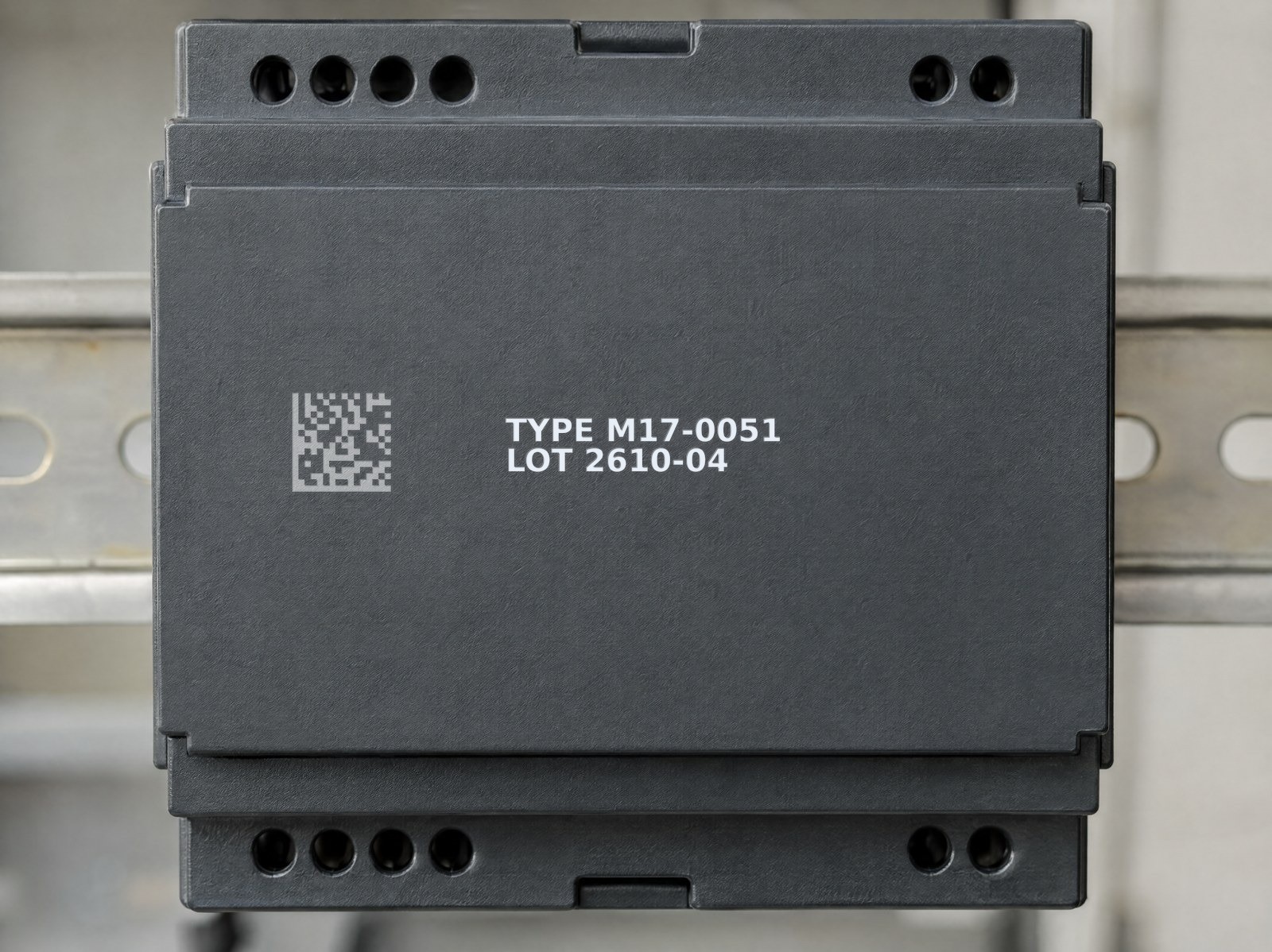
This is where the picosecond pulse changes the way the job is approached: it transfers energy over timescales so short that the heat input to the surrounding material becomes negligible, and it does so as a non-contact process, with no mechanical pressure on the component.
Cold ablation: why the thermal impact stays negligible
Traditional fibre marking, with pulses in the order of nanoseconds, works largely by thermal means: the material is heated, melted and partly oxidised. Around the marked point a heat-affected zone (HAZ) forms, in which the heat has spread before dissipating. On a solid metal this is irrelevant; on a plastic package just a few tenths of a millimetre thick, or on a resin encapsulating a chip, that diffusion is precisely what cannot be allowed.
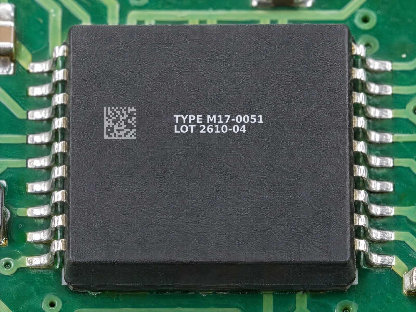
The picosecond pulse reverses the relationship between the time taken to release the energy and the time taken for the heat to spread. The pulse duration is in the order of 10⁻¹² seconds, shorter than the time the heat takes to propagate through the material lattice. The energy removes the surface layer by ablation before it can turn into heat that would warm the surroundings: this is why it is called “cold” ablation. The thermal impact is not eliminated — a residual amount always exists — but it stays negligible, and the HAZ is reduced to a fraction of that of a long pulse. It is no coincidence that the picosecond laser is the established choice wherever marking must be done without glare and without altering the substrate.
Pulse duration Heat-affected zone shorter pulse, smaller HAZFor the process engineer this translates into a far wider working margin: a clean, legible mark is achieved while keeping the substrate well away from the thresholds at which plastics and resins begin to soften, blister or char.
Packages, connectors and resins: marking without attacking the substrate
Electronics materials are unforgiving. The epoxy compounds of packages, the technical thermoplastics of connectors and the encapsulation resins have low thermal thresholds and behave differently from one another: some blister, others discolour uncontrollably, others deform. With a long pulse the trade-off is constant: lowering the energy to avoid damage often means a weak mark, while raising it to make it legible means risking the substrate.
The ultrashort pulse resolves this trade-off because it acts on the very top layer. On packages it modifies the first few microns of the material in a controlled way, generating the contrast without digging deep and without affecting the component’s functionality. On connectors and resins the marking stays confined to the intended area, without propagating stress to the body of the part. It is the same logic that governs the marking of plastics in the electronics sector, where compatibility between source and material determines the quality of the result.
Distance from joints and tracks: the marking layout matters
On an already populated module the marking does not stand alone: it coexists with solder joints, bumps, leads and tracks that must not receive energy. The advantage of picosecond here is twofold. The beam is strongly focused, so the energy stays concentrated in a narrow area; and the negligible lateral heat diffusion means that whatever happens at the marked point does not “spill over” towards the nearby conductors.
A sound design rule nevertheless remains: define a dedicated marking area on the package, with a safety margin from the leads and tracks, and validate it during trials on real samples. This is layout work done once, upstream, that makes the cycle repeatable in production. The FlyCAD software manages the positioning of the content — serial numbers, DataMatrix, logos — within the assigned area, so the marking always falls where it should.
Non-contact process and in-line ESD management
Sensitivity to electrostatic discharge is a handling issue, not just a marking one. Compared with methods that touch the part — punching, dot peen, pad printing with contact — laser marking is a non-contact process: no tool presses on the component, no friction generates charge at the working point, and there is no mechanical wear introducing conductive particulate.
This does not exempt the line from good ESD practice: the component must still be handled in a controlled environment, with earthed equipment and work surfaces and with proper management of the nests and part-carrier pallets. Non-contact marking removes one of the sources of stress — the mechanical and electrostatic one from direct contact — and integrates into automated stations where the part stays in its antistatic housing throughout the cycle.
Contrast and legibility on matt black
Most electronic packages are a matt black: precisely the colour on which a legible, stable code is hardest to achieve. With the picosecond pulse the contrast comes from a controlled surface modification, which produces a clear, crisp and non-iridescent mark: the code keeps the same contrast from any viewing angle, an essential condition for the automatic reading of DataMatrix codes in line.
The stability of the contrast is what distinguishes a mark that passes inspection from one that generates false rejects. A DataMatrix on a black package must remain legible after handling and downstream treatments; cold marking, based neither on surface oxidation nor on a deep recess, offers contrast that is constant over time. Formal verification of code quality requires controlled laboratory conditions, whereas in-line grading remains the practical tool for keeping legibility under control during production.
When UV is preferable to picosecond
Picosecond is not the answer to every marking task in electronics, and it is only fair to say so. Its strength is its versatility across mixed substrates — metal, packages, resins, dark surfaces — with negligible thermal impact. But when the part is a light or transparent plastic, or a polymer particularly reactive to short wavelengths, the UV laser at 355 nm works by predominantly photochemical absorption and often produces better contrast with even less energy in play: this is the domain of the UV laser for plastics.
| Criterion | Picosecond fibre (1064 nm) | UV (355 nm) |
|---|---|---|
| Predominant mechanism | Ultrashort-pulse ablation, negligible heat input | Photochemical absorption, low energy in play |
| Ideal materials | Mixed metal-plastic substrates, packages and resins, dark surfaces | Light and transparent plastics, thin films, sensitive polymers |
| Contrast on matt black | High and non-iridescent, stable over time | Good on many plastics, variable on heavily loaded blacks |
| In-line strength | One source for heterogeneous product families | Maximum gentleness on light polymers |
The choice, in practice, is made on the material and the required result, not on principle. On dark packages and connectors, on mixed substrates and wherever a single source is needed for heterogeneous product families, picosecond is the most rational solution. On light plastics, thin films and components where even the slightest heat input must be avoided, it is worth considering UV. On many lines the two technologies coexist, each on the job it does best.
In short: if you mark sensitive electronic components — black packages, connectors, populated modules — and the problem is obtaining legible codes without thermal damage and without contact stress, picosecond fibre tackles exactly this. The validation must be done on your own materials, with trials on real samples: that is where the process margin is truly measured.

Applications Manager | LASIT
Applications Manager at LASIT for over 20 years, Mario Palmieri oversees the management and development of the company’s laser laboratory. He is responsible for conducting sample tests for customers, supporting the automotive, medical, aerospace and electronics sectors in identifying the most suitable laser marking solution for their needs.


