
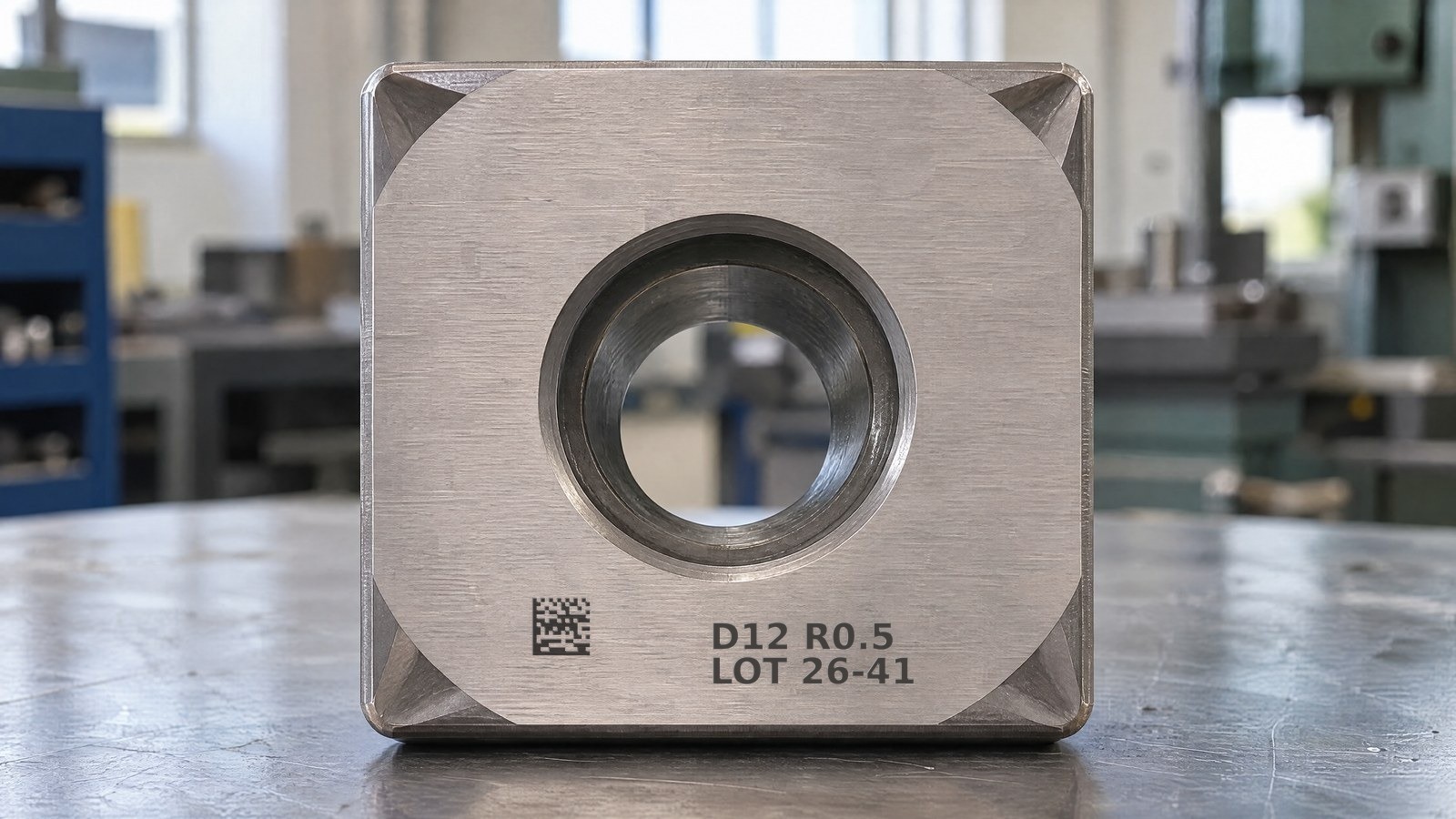
Anyone producing turning inserts, solid end mills and small cutting components knows the same constraint well: fitting a legible DataMatrix and an alphanumeric string into a few square millimetres, on a face that is sometimes less than a centimetre across. The code must stay readable for an in-line reader even after regrinding, coating and the first hours of use; the string must be readable by eye or with an OCR system. On surfaces this small the margin for error is minimal.
The instinct, when a mark “won’t read”, is to turn up the power. At these dimensions this is almost always the wrong move: more energy widens the trace, tends to burn the edges of the modules and reduces the contrast between a filled cell and an empty one, worsening precisely what you set out to improve. The factor that decides whether a DataMatrix with a cell below half a millimetre is readable — or whether a line of text a few hundred microns high stays crisp — is not the number of watts, but the spot size, that is the focal length and the scanning optics.
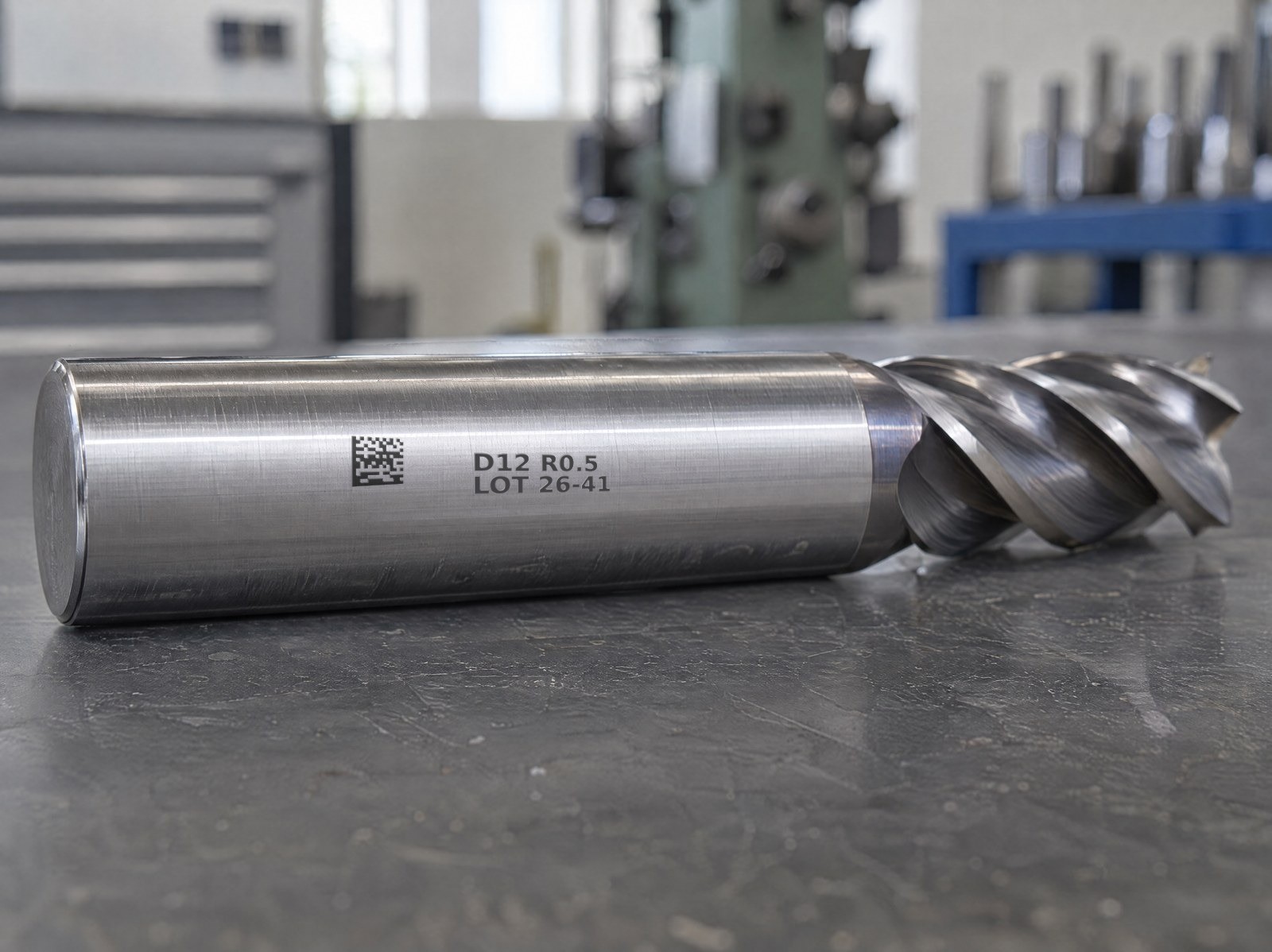
Why it isn’t the watts that make the micro-engraving
Power governs how much energy reaches the material per unit of time: it serves to set the contrast, the depth and the process speed, but not the fineness of the line. The smallest detail the laser can write is fixed by the diameter of the focal spot: at the same spot size, increasing the power widens the area actually worked — thermal edge, module bleed — it does not make it finer. On a tool, moreover, you aim for the least possible material removal so as not to weaken the cutting edge or damage the coating: the goal is maximum contrast at minimum fluence. Micro-engraving is therefore first and foremost a problem of optical resolution, not of energy.
Spot, focal length and field: the relationship that governs resolution
The spot is smaller the shorter the wavelength and the focal length of the optics, and the wider the beam entering the lens. It is a zero-sum relationship with the working field: a short focal length concentrates the beam into a small, high-density spot, ideal for fine detail, but narrows the marking field and reduces the depth of field; a long focal length covers a wide field but with a larger spot. Telecentric lenses keep the beam perpendicular across the whole field, with a uniform spot from centre to edges — a valuable condition when marking on tiny surfaces. Anyone wishing to explore the link between focal distance and depth of field will find the full picture here.
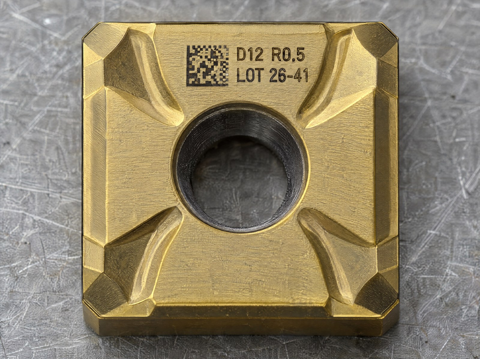
This is precisely the operating point: on an insert or an end-mill shank the usable field is tiny, so you can choose a short focal length with a narrow field and obtain a fine spot. The lever is the optics, not the power supply.
Minimum line thickness and DataMatrix cell
The minimum thickness of a line coincides, in practice, with the spot size plus the process spread: you cannot go below that value, however much power you use. The same reasoning applies to a DataMatrix for each single cell: for the code to be resolvable both in marking and in reading, the module must stay comfortably larger than the spot, so that a filled cell and an empty cell come out clearly distinct. When the cell drops below half a millimetre, the margin between spot and module thins out and the quality of the code suffers. The process rule is to size the code so that each module is worth several spots, never just one: if there is no room, either you reduce the spot — shorter focal length, or a shorter wavelength — or you reduce the data to be encoded to leave larger cells.
The right fonts for micro-engraving
Below a millimetre the typographic choice counts as much as the laser parameters. Characters with uniform stroke thickness work best, where every line has the same width as the spot and the result is predictable; fonts with serifs and strong contrast between thick and thin strokes should be avoided, because the fine strokes disappear as soon as they drop below the spot size. It helps to favour open counters and a good x-height, so the letters don’t close up into a single solid blob. And above all keep the text short: batch and serial, not lengthy descriptions. Fewer characters means each one is larger, and therefore more legible — by eye as for OCR.
When you need UV at 355 nm
As long as the surface allows it, the 1064 nm fibre source handles the vast majority of marking on tools. When, however, the spot itself becomes the bottleneck — the smallest cell, the thinnest line — the wavelength comes into play. At 355 nm the beam focuses into a smaller spot than at 1064 nm with the same optics, because the minimum spot diameter scales with the wavelength. On top of that, the interaction of UV with the material is markedly “cold”, with limited heat input: an advantage on sensitive coatings and on delicate cutting edges. UV remains the choice reserved for the most extreme detail and for delicate materials, not the first-line solution.
| Parameter | Fibre 1064 nm | UV 355 nm |
|---|---|---|
| Wavelength | 1064 nm | 355 nm |
| Minimum focusable spot | Larger | Smaller |
| Heat input at the edge | Greater | Limited |
| Role in micro-engraving | Standard for most cases | Most extreme detail and delicate materials |
In-line grading, laboratory verification: two different checks
When you push a code to the limit of its size, you need to know whether it is genuinely readable — and the two checks available answer different questions. Grading assesses the quality of the code against a standardised scale (ISO/IEC 15415 for 2D codes, AIM DPM for direct part marking) and can be carried out in line with a vision system, assigning a grade to each part that passes. Verification is another matter: it requires controlled laboratory conditions — calibrated lighting, optics and instrument — and certifies conformity in a repeatable way. It is not an in-line check. On micro-engraved codes the distinction is decisive: a DataMatrix that achieves an acceptable grading in line may require laboratory verification to confirm that it reaches the grade the customer requires. The difference between reading, grading and verification is the point not to get muddled over.
When it is better to keep only the code (and who it is designed for)
There is a point at which text and 2D code compete for the same few square millimetres. When the DataMatrix module is already close to the spot limit, adding a legible line of text forces you either to widen the code area — space the insert doesn’t have — or to reduce both below the reliability threshold. In such cases the correct engineering choice is to drop the plain text and keep only the DataMatrix, which packs batch, serial and part code into a footprint that a scanner resolves better than the eye. The text is kept only when an operator has to read it without an instrument.
Micro-engraving optimised on the spot is designed for those marking inserts, end mills and small cutting components with traceability requirements on small surfaces, where the marking of end mills and tools must stay readable downstream of coatings and wear. There is no need to push towards the smallest spot or towards UV when the surface is large and the standard fibre already resolves the code with margin to spare: in those cases you complicate the process with no gain. But when the face to be marked is tiny and the code has to withstand reading and grading, the factor to work on is the spot — the focal length and the optics — not the watts.

Applications Manager | LASIT
Applications Manager at LASIT for over 20 years, Mario Palmieri oversees the management and development of the company’s laser laboratory. He is responsible for conducting sample tests for customers, supporting the automotive, medical, aerospace and electronics sectors in identifying the most suitable laser marking solution for their needs.


