

Anyone producing aerospace components subject to cyclic loads — structural brackets, fittings, fuselage elements, landing-gear attachments in titanium or aluminium alloy — lives with an unwritten rule: every discontinuity on the surface of a fatigue-loaded part is a potential crack initiation site. A sharp corner, a scratch, a groove left by machining become stress concentrators, the points from which a fracture can propagate under repeated loading.
Marking lives right inside this contradiction. The component has to be identified permanently — UID code, DataMatrix, serial, batch reference — because traceability is a compliance requirement even before it is a process one. But marking is also a local modification of the surface: on a fatigue-loaded part, a poorly executed mark can weaken the very component it is meant to make traceable.
The decisive point is a distinction that often stays implicit: the difference between an aesthetic requirement and a structural requirement of the mark. This is where annealing — annealing marking, with no material removal — becomes the correct technical answer.
Why a mark can become a crack initiation site
A component’s fatigue strength depends not only on the material and the loads, but on the state of its surface. Every geometric notch acts as a stress concentrator: locally the real stress exceeds the nominal design value, and on a metal working through millions of cycles it is precisely from those points that the first microcrack is born. An engraving or deep engraving mark removes material and leaves a groove with sharp edges: a notch to all intents and purposes.
On a riveted-on plate or in an unloaded area this is not a problem. On a structural surface of a titanium alloy or a high-strength aeronautical aluminium, however, that groove can reduce the part’s fatigue life. This is why many aerospace drawings treat marking as a design feature, not as a shop-floor operation left to the operator’s discretion. The same logic guided the transition from dot peen to laser: micro-dot punching plastically deforms the material and introduces residual stresses exactly where they are not wanted.
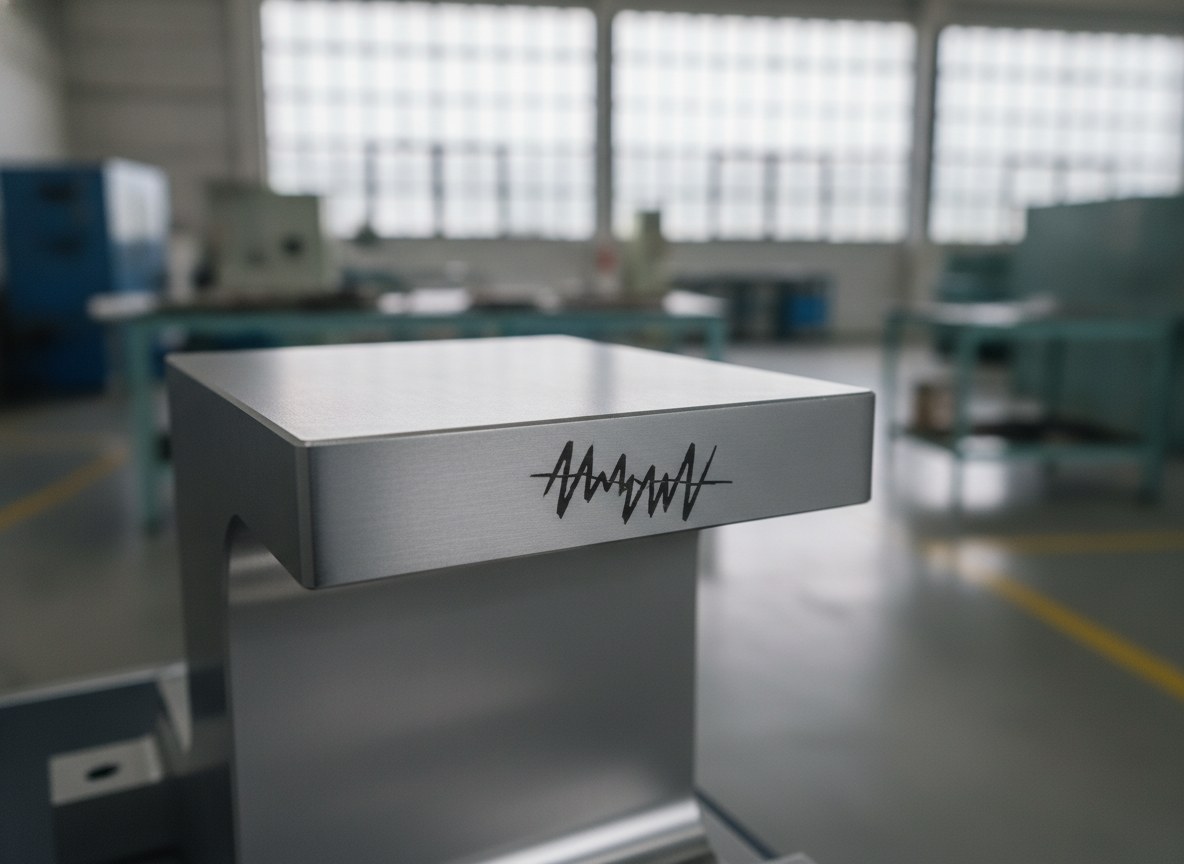
Aesthetic versus structural: two requirements for the same code
A DataMatrix code marked on a skin panel and a code marked on a spar look like the same thing, but they answer opposite requirements. In the first case what matters is legibility over time, contrast, resistance to environmental agents: it is an aesthetic and functional requirement. In the second case what matters as well — and above all — is that the mark does not alter the mechanical behaviour of the part: it is a structural requirement.
Confusing the two levels leads to typical mistakes. An engraving depth is chosen “to be safe”, thinking that deeper means more permanent, and a notch is introduced where a zero-impact mark was needed instead. Or the very same cycle is applied to a visible surface and to a loaded surface, ignoring that the technical constraint is different. Correct marking starts from the right question: is this surface fatigue-loaded, yes or no?
How annealing works: contrast without removing material
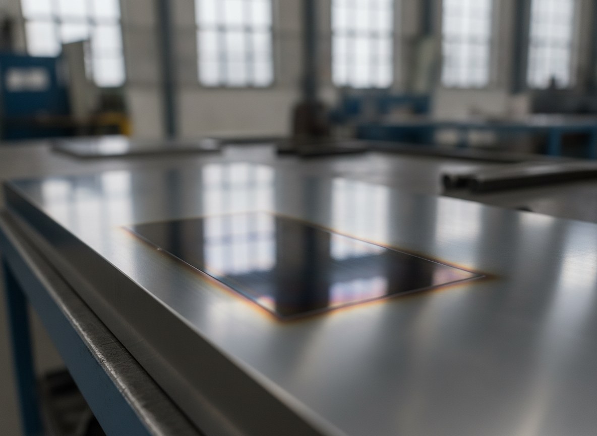
Annealing uses the controlled heat of the beam to heat the metal below the melting and vaporisation threshold. Under these conditions no material is removed: it triggers the growth of a thin oxide layer beneath the surface, which produces a dark contrast or a stable tone through optical interference. The result is a permanent mark in which the surface profile remains unchanged: no groove, no sharp edge, no displaced material.
This is the substantial difference compared with engraving. Where engraving creates a geometric discontinuity, annealing leaves the surface coplanar with the original one: to the touch and to the profilometer the marked area and the surrounding one belong to the same plane. For a fatigue-loaded component this means that the stress concentrator, quite simply, is not there. Process control is demanding, however: the window between a well-formed oxide and the onset of localised melting is narrow, and it requires qualified, repeatable parameters, not settings judged by eye.
| Aspect | Engraving / deep marking | Annealing (no material removal) |
|---|---|---|
| Material removal | Yes, creates a groove | No, no removal |
| Effect on the surface profile | Geometric discontinuity | Profile unchanged |
| Fatigue initiation risk | Present on loaded areas | Negligible |
| Mark contrast | High and permanent | High, from controlled oxidation |
| Recommended surfaces | Non-structural areas | Also fatigue surfaces (with design constraints) |
Depth, surface integrity and marking zones
On aerospace components depth is not a free parameter. Product specifications often define a maximum limit for direct marking on loaded surfaces, and on some classes of component material removal is simply not permitted. Annealing naturally falls within these constraints because it operates at negligible depth and does not affect the metal substrate.
The second constraint concerns zones. The component drawing typically distinguishes areas where marking is allowed — non-structural surfaces, low-stress areas, riveted-on plates — and areas where it is forbidden or limited to zero-impact methods. Marking thus becomes a design choice traced on the drawing, not a shop-floor decision.
When the code serves to support traceability throughout the part’s whole life — as in the logic of UID codes across the component life cycle — the objective is a mark that stays legible and verifiable for years without having touched the structural integrity. The opposite case, that of multi-level deep marking, remains valid but on an entirely different family of components: those where depth is intended and the surface is not fatigue-critical.
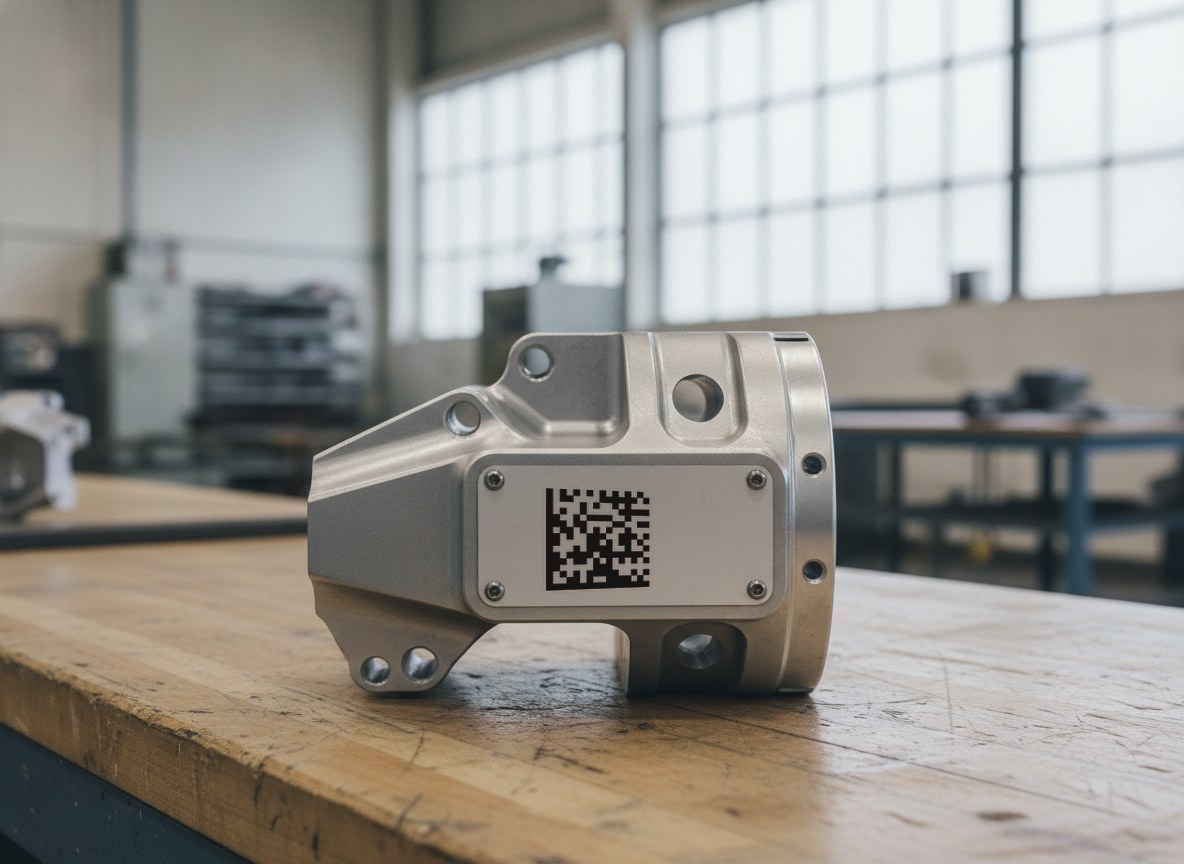
Titanium and aluminium: two alloys, two behaviours
Titanium alloys are the natural ground for annealing. Titanium oxide forms in an orderly and stable way, and depending on its thickness it generates crisp, repeatable tones with no material removal whatsoever. On a fatigue-loaded titanium component you thus obtain a high-contrast code while leaving the surface perfectly coplanar, the ideal condition when the part must retain its design fatigue life.
Aeronautical aluminium alloys behave differently: their high thermal conductivity dissipates heat rapidly and the native oxide has its own dynamics, so the classic colour annealing typical of titanium is not the reference mechanism. Here too, though, the guiding principle stays the same: on a fatigue surface the priority is a very-low-penetration mark that generates contrast without creating a notch. Parameter selection must be calibrated to the specific alloy, and for this reason the obligatory route is trials on real samples of the customer’s material, not generic settings.
Documenting the process for the technical file
In aerospace a marking process is worth as much as its documentation. It is not enough for the code to be legible: it must be possible to demonstrate that the applied cycle did not compromise the component’s integrity and that it is repeatable. This means starting from qualified parameters, validating them with trials on representative samples, verifying that the marked surface retains its profile and checking the code’s legibility against objective criteria.
Qualification and documentation flowQualified parametersSample testsSurface integrity checkCode readabilityTechnical file recordDataMatrix code grading, applicable in line, provides an objective and repeatable measure of mark quality that feeds into the file; formal verification, when required, is instead carried out under controlled laboratory conditions. Recording parameters, trial outcomes and the acceptance criterion turns marking from a manual operation into a qualified process — the only one that withstands an audit and that integrates with the requirements of the AS9100 and MIL-STD-130 standards.
When annealing is the right choice (and when it is not)
Annealing is the natural solution when the mark falls on a fatigue-loaded surface and the requirement is structural before it is aesthetic: titanium components, alloy elements that must keep their fatigue life intact, parts on which material removal is not permitted. In these cases marking without touching the profile is not an incidental advantage, it is the very condition for being able to mark at all.
It is not, however, the obligatory choice when the surface is not critical and high depths are needed — to withstand severe abrasion, reworking or treatments that remove a surface layer: there a deep mark on a non-structural area remains more suitable. The practical rule is simple: first establish whether the surface is fatigue-loaded, then choose the method. Reversing the order is the mistake that, on an aerospace component, costs the most.

Applications Manager | LASIT
Applications Manager at LASIT for over 20 years, Mario Palmieri oversees the management and development of the company’s laser laboratory. He is responsible for conducting sample tests for customers, supporting the automotive, medical, aerospace and electronics sectors in identifying the most suitable laser marking solution for their needs.


