

Anyone who manufactures hydraulic cylinders, control units and fittings knows the moment when identification becomes a problem: the component is assembled, tested, ready for despatch, and it is precisely at that point that the serial number, nameplate data and traceability code have to be applied. The nameplate is the traditional choice, but on a body working immersed in oil, amid vibration and thermal cycles, it does not always hold up — and in a number of specifications it is not even permitted, for reasons of space, of anti-tampering, or because the reference surface is the rod itself.
Direct fibre marking solves the problem at the root, because it writes the information onto the metal and not onto a carrier that can come away. But applying it to an already-assembled component means having to consider two constraints that no data sheet resolves on its own: access to the surface to be marked and the risk of circuit contamination. It is these two points, not the power of the source, that decide whether the project works.
Why the nameplate does not always hold up in hydraulics
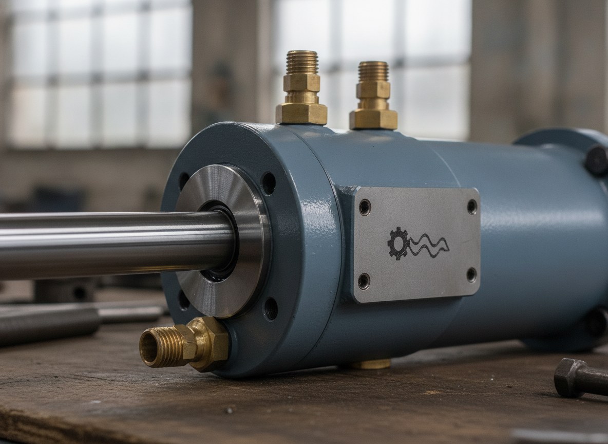
An applied nameplate is an added component, and like every added component it has a way of failing. Adhesives give way under prolonged contact with mineral oils and hydraulic fluids; riveted or crimped nameplates can work loose under vibration; the thermal cycle between start-up and working temperature fatigues both the bonding agent and the mechanical interface. The result is the loss of the reference just when it is needed: during servicing, a return or the analysis of a fault.
Then there is the question of space. On a fitting, a head or a compact cylinder the available flat surface is minimal, and a nameplate takes up usable area that is often simply not there. In other cases it is the customer’s specification that requires the data to be engraved on the body, to ensure that identification and component remain one and the same throughout the life of the part. Direct marking was created precisely for this scenario: it makes the data inseparable from the metal.
Direct fibre marking on steel and chromed surfaces
The 1064 nm fibre source is the natural choice on hydraulic metals: it marks carbon steels, stainless steel, brass and treated surfaces with a single type of machine, adapting the result to the material. On these components the decisive variable is not what can be written, but how it is written without compromising the functional surface.
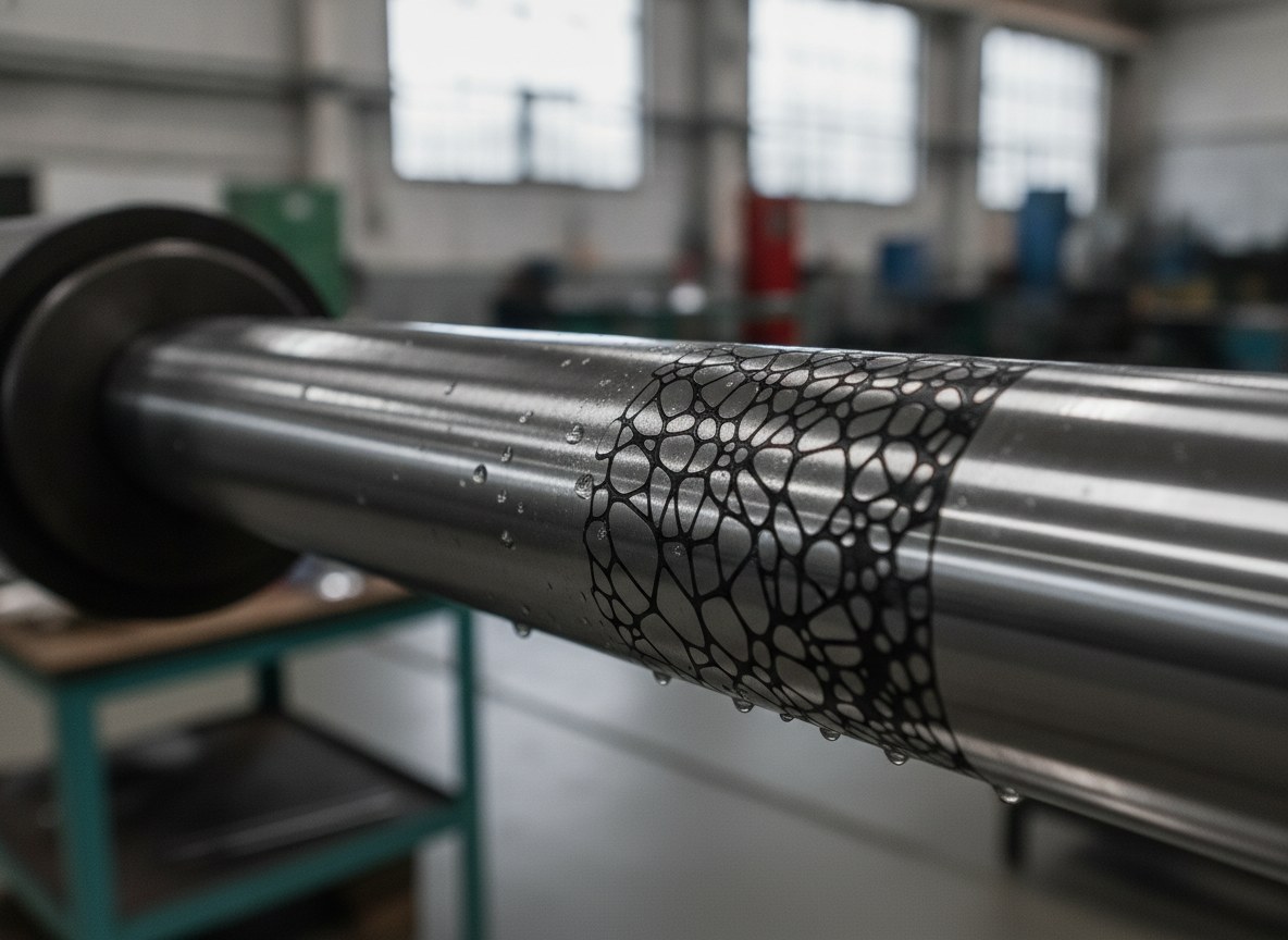
On a chromed rod the issue is clear-cut. The hard chrome layer, often a few microns thick, is what protects the rod from corrosion and from wear by the seal pack: engraving it deeply means opening a path to corrosion in the very area where the rod slides. This is why, where the surface is critical, annealing marking is preferred: the beam heats the metal below the melting threshold and generates a stable dark contrast without removing material, leaving the surface intact. True engraving, on the other hand, remains suited to bodies and heads, where a deeper mark improves legibility and abrasion resistance without touching sealing areas.
The access constraint: marking without dismantling
On an assembled component you cannot bring the part to the machine as you would on the line: it is the marking head that has to be brought to the part. Here what matters is the working distance and the depth of field of the optical system, which must be sufficient to reach surfaces recessed between flanges, fittings and connections without collisions and while maintaining correct focus.
On cylindrical bodies — rods, tubes, bushes — the problem is curvature. Marking over a wide field on a round surface distorts the characters and disperses power density at the edges; this is why a rotary axis is used to turn the part while keeping the beam always perpendicular to the surface, so the marking stays uniform right around the circumference. Where the geometry is irregular or inclined, a 3D head makes it possible to follow the profile without moving the component, as already happens with marking on curved and irregular surfaces. The common principle is just one: adapt the system to the assembled part, not the other way round.
The risk of particulate and circuit contamination
Marking a component already connected to a hydraulic circuit introduces a risk that does not exist on the line: particulate. Any process that removes material generates debris, and in hydraulics a micro-contamination entering an open connection can damage seals, valves and sliding surfaces. This is why the choice of marking process, in this context, is also a choice about cleanliness.
Direct marking on an assembled component without contaminationMask portsPosition rotary axisAnneal markingFume extractionCode gradingAnnealing marking is advantageous here too, because it does not remove metal and therefore produces no solid debris. Where engraving is needed, control is achieved by combining localised fume extraction with the masking or temporary closure of ports and connections near the marking area. In many cases the safest solution remains marking the components before the circuit is closed, reserving in-situ marking for those cases alone where the data must be applied to the finished assembly.
Direct marking or nameplate: an honest comparison
Direct marking does not make the nameplate obsolete: they are two tools with different logics. Direct marking is permanent, does not come away, is unaffected by oils or thermal cycles and binds the data to the part; however, it requires a suitable, accessible surface and enough flat space for the code. The nameplate carries far more information, can be standardised and can be updated or replaced, but it is an element that can be lost, work loose or be removed.
| Aspect | Direct fibre marking | Applied nameplate |
|---|---|---|
| Permanence | Tied to the metal, not removable | Added element, can come away or be lost |
| Resistance to oil and thermal cycles | High, no adhesive or interface | Depends on bonding agent and fixing |
| Space required | A small suitable flat surface is enough | Requires a dedicated area on the component |
| Amount of data | Suited to serial number and 2D code | Suited to extensive data and complex layouts |
| Updatability | Fixed over time | Replaceable in the event of revision |
The same applies to code traceability. A DataMatrix marked directly on the metal must be designed for reading on the real material: the grading according to the applicable in-line standards (ISO/IEC 15415 and AIM-DPM for direct part marking) must be verified on the actual surface, which on chromed steel or a painted body responds differently to a nameplate with controlled contrast. When, on the other hand, the requirement is to manage extensive data and an automatic flow towards ERP and MES, the route of the laser-marked nameplate remains fully valid.
When dismantling or the nameplate remains the correct choice
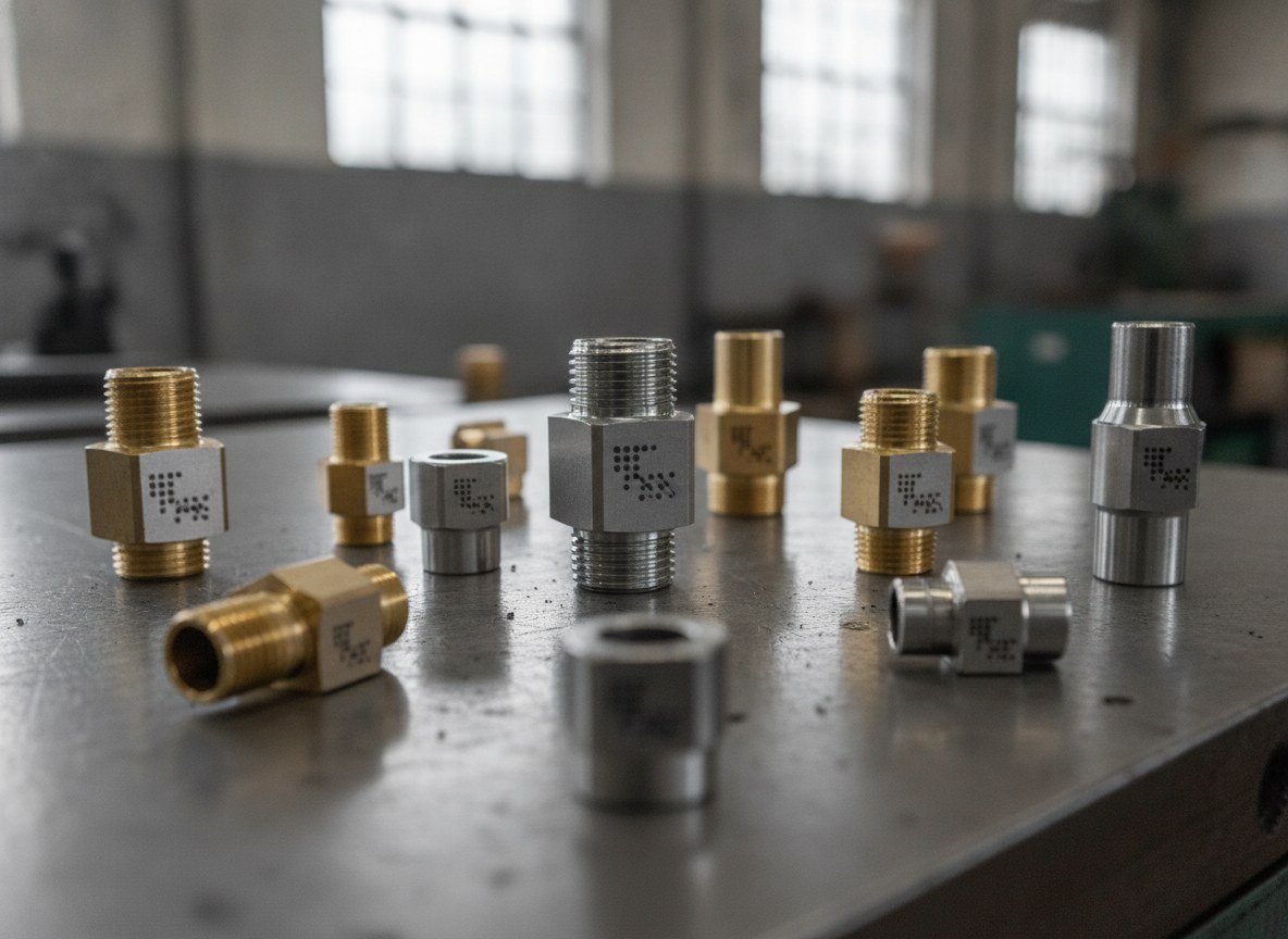
Direct fibre marking on assembled components is the right solution when the metal surface is accessible, suitable and not critical for sealing, and when the data must stay tied to the part throughout its life. It is the typical case of rods, tubes, heads, blocks and fittings in steel or brass on which a serial number or a DataMatrix must survive oil, vibration and servicing.
It is not, however, the route to force in three situations. When the usable surface is painted or coated in such a way that a legible mark would require breaching the protection, a separate nameplate makes more sense. When the specification or the sector standard requires a metal data plate with extensive information, that remains a requirement, not an option. And when the area to be marked cannot be reached on the assembly without a contamination risk that cannot be managed, the correct choice is to pre-mark the components before assembly or, where necessary, to dismantle. Recognising these cases is as much part of the solution as knowing how to mark without dismantling.

Business Development Director | LASIT
Business Development Director at LASIT, Giandomenico Ievoli is responsible for the commercial direction and strategic development of the company. He leads business development activities at national and international level, contributing to the growth and expansion of LASIT in global markets.


